March 14, 2016  Expand to read article below Expand to read article belowThere is a chance that you will need to read multiple analog signals at once or are the analog signals you are reading too small? The dsPIC3EPxxGS50x family of microcontrollers solve both of these problems, and the CCS C Compiler makes it easy to use. This family of chips have new ADC capable of sampling up to 5 analog inputs simultaneously. With the addition of two new functions for setting up the dedicated ADC cores, the Compiler makes it simple to read a single channel or multiple channels simultaneously. The following is an example of how to setup the ADC to read AN0 using the Dedicated ADC Core 0:
setup_adc_ports(sAN0, VSS_VDD);
setup_adc(ADC_CLOCK_SYSTEM | ADC_CLOCK_DIV_1 | ADC_WARMTIME_512);
setup_dedicated_adc(0, ADC_DEDICATED_CLOCK_DIV_2 |
ADC_DEDICATED_TAD_MUL_257 |
ADC_DEDICATED_CORE_CONV_DELAY);
set_dedicated_adc_channel(0, ADC_CHANNEL_AN0);
while(TRUE)
{
ADCReading = read_adc(ADC_START_AND_READ, 0);
... }
Since the dsPIC33EPxxGS50x family of devices have individual Data Ready Status flags and Buffer registers for each analog channel, an optional second parameter was added to the read_adc() function to specify the channel to read. This allows for quicker reads with far less code generated to determine the flag to test and buffer to read.
Additionally the dsPIC33EPxxGS50x family have two Programmable Gain Amplifiers (PGA). The PGA is an op amp based non-inverting amplifier that can be used to amplify small voltages by 4x, 8x, 16x, 32x or 64x to improve the signal-to-noise ration of the measured signal. The PGA output voltage can then be read by one of the dedicated cores of the of the ADC, or used as an input to the Analog Comparator.
The new built-in functions are available in IDE compilers and the PCM command-line compilers starting with version 5.056.
Like us on Facebook. Follow us on Twitter.
About CCS:
CCS is a leading worldwide supplier of embedded software development tools that enable companies to develop premium products based on Microchip PIC ® MCU and dsPIC ® DSC devices. Complete proven tool chains from CCS include a code optimizing C compiler, application specific hardware platforms and software development kits. CCS' products accelerate development of energy saving industrial automation, wireless and wired communication, automotive, medical device and consumer product applications. Established in 1992, CCS is a Microchip Premier 3rd Party Partner. For more information, please visit http://www.ccsinfo.com.
PIC ® MCU, MPLAB ® IDE, MPLAB ® ICD2, MPLAB ® ICD3 and dsPIC ® are registered trademarks of Microchip Technology Inc. in the U.S. and other countries. | March 14, 2016 Expand to read article below Ever wanted more accuracy in the output of your PWMs? The new PIC16F1574 and PIC16F1764 family of devices both have a 16-bit PWM peripheral. The advantage of using a 16-bit PWM is that it increases the resolution of the PWM signal allowing for more precise duty cycles. Additionally each 16-bit PWM peripheral has an independent timer, this allows for generating the PWM without using one of the device's timers. The CCS C Compiler supports the new 16-bit PWM peripheral using either built-in functions or the #use pwm() library. The following is an example of how to use the #use pwm() library to setup the 16-bit PWM peripheral on a PIC16F1574:
#include <16F1574.h>
#fuses NOWDT
#use delay(internal=8MHz)
#use pwm(output=PIN_C3, frequency=122Hz, bits=16, duty=50)
void main()
{
for(;;); }
Because the 16-bit PWM peripheral has an independent timer and registers for setting the PWM signal's phase and offset, the following built-in functions have been added to the CCS C Compiler to set the period, phase and offset:
SET_PWMx_PERIOD() //x being the PWM peripheral
SET_PWMx_PHASE() //x being the PWM peripheral
SET_PWMx_OFFSET() //x being the PWM peripheral
The following is an example of how to use the built-in functions to setup the 16-bit PWM peripheral:
#include <16F1574.h>
#fuses NOWDT
#use delay(internal=8MHz)
#pin_select PWM1=PIN_C3
void main()
{
set_pwm1_period(0xFFFF); //8.192ms period, ~122Hz frequency
set_pwm1_duty(0x7FFF); //50% duty
setup_pwm1(PWM_STANDARD);
for(;;); }
The new built-in functions are available in IDE compilers and the PCM command-line compilers starting with version 5.056.
Like us on Facebook. Follow us on Twitter.
About CCS:
CCS is a leading worldwide supplier of embedded software development tools that enable companies to develop premium products based on Microchip PIC ® MCU and dsPIC ® DSC devices. Complete proven tool chains from CCS include a code optimizing C compiler, application specific hardware platforms and software development kits. CCS' products accelerate development of energy saving industrial automation, wireless and wired communication, automotive, medical device and consumer product applications. Established in 1992, CCS is a Microchip Premier 3rd Party Partner. For more information, please visit http://www.ccsinfo.com.
PIC ® MCU, MPLAB ® IDE, MPLAB ® ICD2, MPLAB ® ICD3 and dsPIC ® are registered trademarks of Microchip Technology Inc. in the U.S. and other countries. | May 22, 2015 Expand to read article below Built-in functions have been added to the CCS C Compiler for setting up and using the PID module introduced for the PIC16F1614 family of devices. The PID module is a mathematics module that can perform a variety of operations, most prominently acting as a PID (Proportional-Integral-Derivative) controller.
The module accomplishes the task of calculating the PID algorithm by utilizing user-provided coefficients along with a multiplier and accumulator. The main benefit of using the PID module is for the PID calculation to be completed much faster with the hardware module than in software. For example when running the PIC® from the 32 MHz internal oscillator the built-in HW PID function was measured to take 12.8 us, compared to a software PID function which was measure to take 216 us. This is approximately 1/16 of the time.
The following are the built-in functions that have been added for the PID module:
- setup_pid() - used to setup the PID module and set the user-input coefficients.
- pid_get_result() - used to input the set point and feedback from the external system to the PID module, start the calculation, and to retrieve the result to input in the external system.
- pid_read() - used to read various PID module registers.
- pid_write() - used to write various PID module registers.
- pid_busy() - used to check if PID module is busy or not-busy, finished, with calculation.
The user-input coefficients, K1, K2 and K3, are calculated from the three classic PID coefficients Kp, Ki and Kd with the following equations:
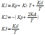
T is the sampling period.
The following is an example of how to setup and use the PID module:
void main(void) {
pid_struct_t PIDOutput;
unsigned int16 ADCReading;
signed int16 K1 = 7, K2 = -6, K3 = 0;
unsigned int16 SetPoint = 500;
unsigned int16 PWMDuty;
setup_pid(PID_MODE_PID, K1, K2, K3);
//Setup ADC
setup_adc_ports(sAN3, VSS_VDD);
setup_adc(ADC_CLOCK_INTERNAL);
set_adc_channel(3);
//Setup PWM 3
setup_timer_4(T4_CLK_INTERNAL | T4_DIV_BY_32, 249, 1); //1ms period, from 32 MHz clock
set_pwm3_duty(0); //0% duty
setup_pwm3(PWM_ENABLED | PWM_OUTPUT | PWM_TIMER4);
while(TRUE) {
delay_ms(50);
ADCReading = read_adc();
pid_get_result(SetPoint, ADCReading, &PIDOutput);
PIDOutput.u &= 0x07;
if(PIDOutput.u >= 4) //PIDOutput is negative, set PWMDuty to Minimum
PWMDuty = 0; else if(PIDOutput.u != 0) //PIDOutput > Maximum, set PWMDuty to Maximum
PWMDuty = 1000; else if(PIDOutput.l > 1000) //PIDOutput > Maximum, set PWMDuty to Maximum
PWMDuty = 1000; else
PWMDuty = PIDOutput.l;
set_pwm3_duty(PWMDuty); } }
The new built-in functions are available in IDE compilers and the PCM command-line compilers starting with version 5.045.
Like us on Facebook. Follow us on Twitter.
About CCS:
CCS is a leading worldwide supplier of embedded software development tools that enable companies to develop premium products based on Microchip PIC ® MCU and dsPIC ® DSC devices. Complete proven tool chains from CCS include a code optimizing C compiler, application specific hardware platforms and software development kits. CCS' products accelerate development of energy saving industrial automation, wireless and wired communication, automotive, medical device and consumer product applications. Established in 1992, CCS is a Microchip Premier 3rd Party Partner. For more information, please visit http://www.ccsinfo.com.
PIC ® MCU, MPLAB ® IDE, MPLAB ® ICD2, MPLAB ® ICD3 and dsPIC ® are registered trademarks of Microchip Technology Inc. in the U.S. and other countries. | May 22, 2015 Expand to read article below Starting with version 5.046 of the CCS C Compiler and version 5.018 of CCSLOAD programming software has made it easy to create Unicode strings and write a user-provided serial number to the USB device descriptor during programming. In the device descriptor of a USB device a serial number string can be provided, but this is optional. If a serial number is provided in the device descriptor, two or more USB devices attached to a host cannot contain the same VID/PID/serial combination. Since USB has a mechanism for storing and reading serial numbers, it may be advantageous to a developer to use this mechanism instead of developing a custom mechanism on top of whatever USB protocol is being used. A challenge with using the standard USB mechanism, however, has been programming a user provided serial number due to the string being in Unicode and having the Unicode string packed in a table with other strings in the string table with a length field in front of the string. All of these problems have been solved in the latest tools from CCS.
First, a new pre-processor has been added to the CCS C Compiler:
_unicode(x)
When called, it converts the string x to a UTF-16 Unicode string. This is the format used by string descriptors in USB. For example:
char string[] = _unicode("Hello");
Since "Hello" is an ASCII string (no character has a value greater than 0x7F), all characters encoded will be 16bit - therefore the size of string[] would be the strlen("Hello")*2. string[], when in Unicode, will not be null terminated. It is not null-terminated since 0x00 is a valid character in UTF-16 and not a null-terminator. That means to get the string length of string[] the user would have to use sizeof() instead of strlen().
Second, the #serialize() pre-processor has been updated in the CCS C Compiler to tell the CCS CCSLOAD programming software how to serialize a Unicode string. The new parameter added is unicode, which tells the #serialize which USB string to write during programming with the user provided serial number. Here is an example:
#serialize(id=USB_STRING_DESC, unicode=3, prompt="SN#")
USB_STRING_DESC is a table of USB strings and is read by the CCS C Compiler's USB stack when the host PC reads a string from the PIC ®. A value of 3 is passed to the Unicode parameter, to tell the #serialize that the serial number should be encoded as a Unicode string and that it should overwrite the 4th string in USB_STRING_DESC (the first string in USB_STRING_DESC is 0). In the device descriptor for your USB device, the field identifying which string to use for the serial number should also have been set to 3.
A working example of this is provided in the file ex_usb_hid.c. When compiled and programmed onto the PIC ®, CCSLOAD will ask the user for the serial number and write the serial number onto the string descriptor used for the serial number.
Like us on Facebook. Follow us on Twitter.
About CCS:
CCS is a leading worldwide supplier of embedded software development tools that enable companies to develop premium products based on Microchip PIC ® MCU and dsPIC ® DSC devices. Complete proven tool chains from CCS include a code optimizing C compiler, application specific hardware platforms and software development kits. CCS' products accelerate development of energy saving industrial automation, wireless and wired communication, automotive, medical device and consumer product applications. Established in 1992, CCS is a Microchip Premier 3rd Party Partner. For more information, please visit http://www.ccsinfo.com.
PIC ® MCU, MPLAB ® IDE, MPLAB ® ICD2, MPLAB ® ICD3 and dsPIC ® are registered trademarks of Microchip Technology Inc. in the U.S. and other countries. | March 18, 2015 Expand to read article below Pulse Width Modulation (PWM) capability was first added to the PIC® microcontroller line using the Capture/Compare/PWM (CCP) unit. Since then we have seen the enhanced CCP (ECCP) and a variety of power and motor control PWM modules each with its own features. The newest PWM module is called the Programmable Switch Mode Controller (PSMC). This is the most sophisticated PWM yet and is on new chips like the PIC16F1789.
The PSMC allows for standard PWM, complementary PWM, shutdown control and deadband control like some of the older modules. It also allows for high resolution on the duty and frequency, as well variable frequency. It can for example do 3 phase 6 step PWM.
Input pins, comparator outputs and CCP triggers can be used not only to control shutdown, but to control if the PWM is running, or to start or stop a cycle.
Some PIC® devices have as many as 4 independent units and the units can optionally be synchronized with each other.
The new compiler functions are:
setup_psmc(unit, mode, period, period_time,
rising_edge, rise_time,
falling_edge, fall_time);
psmc_pins(unit, pins_used, pins_active_low);
psmc_duty(unit, fall_time);
psmc_deadband(unit, rising_edge, falling_edge);
psmc_blanking(unit, rising_edge, rise_time, falling_edge, fall_time);
psmc_shutdown(unit, option, source, pins_high);
psmc_freq_adjust(unit, freq_adjust);
psmc_modulation(unit, options);
psmc_sync(slave_unit, master_unit, options);
The following is a short example program that shows off some of the features:
#include <16f1789.h>
#use delay(osc=20mhz)
#define us(time) (int16)(time*(getenv("CLOCK")/1000000))
void main(void) {
setup_psmc(1, PSMC_ECCP_BRIDGE_FORWARD,
PSMC_EVENT_TIME | PSMC_SOURCE_FOSC | PSMC_DIV_2, us(100),
PSMC_EVENT_TIME, us(10),
PSMC_EVENT_TIME, us(35));
psmc_deadband(1, us(2), us(4));
psmc_modulation(1, PSMC_MOD_IN_PIN);
psmc_pins(1, PSMC_A | PSMC_B | PSMC_C | PSMC_D);
setup_adc(ADC_CLOCK_INTERNAL);
setup_adc_ports(sAN0);
set_adc_channel(0);
while(TRUE) { psmc_duty(1, us(((read_adc()*(int16)10)/25)) ); } }
Other examples are included with the compiler download and begin with EX_PSMC_
Like us on Facebook. Follow us on Twitter.
About CCS:
CCS is a leading worldwide supplier of embedded software development tools that enable companies to develop premium products based on Microchip PIC ® MCU and dsPIC ® DSC devices. Complete proven tool chains from CCS include a code optimizing C compiler, application specific hardware platforms and software development kits. CCS' products accelerate development of energy saving industrial automation, wireless and wired communication, automotive, medical device and consumer product applications. Established in 1992, CCS is a Microchip Premier 3rd Party Partner. For more information, please visit http://www.ccsinfo.com.
PIC ® MCU, MPLAB ® IDE, MPLAB ® ICD2, MPLAB ® ICD3 and dsPIC ® are registered trademarks of Microchip Technology Inc. in the U.S. and other countries. | March 18, 2015 Expand to read article below A new version of EZ App Lynx has been released, which encompasses an update to the Android Application on the Google Play store and the EZ App Lynx framework library that comes with the CCS C Compiler. Not only does this update improve stability and reduce communication errors, it also adds many new features.
The most significant improvement is the ability to add styles. In the framework library API, the function EZAppStylesROM() allows the user to add one more style configuration. A style can contain configuration information such as text sizes, colors, spacing, margins and alignment. Once a style configuration has been added, all following UI elements added through the framework library will continue using the previously defined styles. The following example shows how a style was used to change the background color and add a border to each UI element, which was not supported in the previous version of the framework:
Another area of improvement is the handling of strings. A string field can now be added to the screen that contains both a header on the left, and the dynamic content on the right. The text style for the header portion on the left can differ from the text on the right. A string field can also be added that is writable from the smartphone/tablet host, allowing the user to add editable strings. This is done through the new framework function EZAppFieldText(). Also, string fields can be specified to read from EEPROM or other external memory devices. Here is an example of an editable string:

The user now has more options when it comes to creating buttons with the new framework function EZAppAddFieldButtons(). This function empowers the user to create:
* More than one button on the row
* Configure the buttons to fill up the entire horizontal space of the row
* Add an inset status LED on each button
The buttons may be configured to be a one-statue button, where it sends a set bit when the button is being held down on the smartphone/tablet. It will then send a cleared bit when the button is not being held down on the smartphone/tablet.
Buttons also have their own style configuration, using EZAppStylesROM(), for the user to configure the color and appearance of the button. Here is an example of 3 buttons on one row, filling the entire row horizontally, with inset status LEDs:

The Android App now supports the RN4020 Bluetooth module in MLDP mode. The RN4020 is a Bluetooth Low Energy module, and the MLDP mode provides a serial data delivery similar to SPP of Bluetooth Classic modules. Work is in development on an iOS version of the App that supports the RN4020 module (the iOS version will not support SPP like the Android app). The CCS C Compiler provides a new driver for the RN4020 module.
The EZ App Lynx framework allows one to quickly develop smartphone and tablet solutions that communicate with the PICmicro over Bluetooth. For more information about EZ App Lynx, see http://www.ccsinfo.com/ezapp
Like us on Facebook. Follow us on Twitter.
About CCS:
CCS is a leading worldwide supplier of embedded software development tools that enable companies to develop premium products based on Microchip PIC ® MCU and dsPIC ® DSC devices. Complete proven tool chains from CCS include a code optimizing C compiler, application specific hardware platforms and software development kits. CCS' products accelerate development of energy saving industrial automation, wireless and wired communication, automotive, medical device and consumer product applications. Established in 1992, CCS is a Microchip Premier 3rd Party Partner. For more information, please visit http://www.ccsinfo.com.
PIC ® MCU, MPLAB ® IDE, MPLAB ® ICD2, MPLAB ® ICD3 and dsPIC ® are registered trademarks of Microchip Technology Inc. in the U.S. and other countries. | December 4, 2014 Expand to read article below CCS C-Aware IDE now includes the EZ App Lynx library (#include <EZApp.c>). Quickly create a Bluetooth® wireless sensor, or controller, that may be viewed or managed on a paired mobile device - using the EZ App Lynx Android App. The free EZ App Lynx Library was created to shorten the design time for smart Bluetooth® app development. With EZ App Lynx, and no required hardware or software expertise, the library removes the barriers to entry for smartphone app developers who want to take advantage of a growing number of Bluetooth® enabled smartphones and tablets. The new library allows for any GUI, on the App, to be created at run time from a PIC® program. The library offers many useful sensor interface components which allow for: Status Bars, Gas Gauges, Sliders, Buttons, Text Fields, and More...
EZ App Lynx Library Features and Advantages:
- NO App design knowledge required
- Source code libraries included with all CCS C Compilers
- Included with maintenance update download
EZ App Lynx App:
- Available for Android in Google Play Store. (iOS available soon)
- Build your own EZ App Lynx App in minutes with simple C library calls on the PIC®
- Quick and easy prototyping
How It Works:
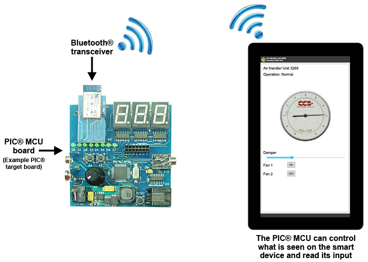
To make use of the EZ App Lynx library and app you'll need a prototyping board with PIC ® MCU and a Bluetooth ® module with SPP - both sold separately. Attach the module to board, and from within the IDE insert the following example code:
--
#include "main.h"
#include <EZApp.c>
void main(void)
{
ezapp_field_index_t strIndex, rpmIndex, damperIndex, fan1Index, fan2Index;
rom char* title = "Air Handler Unit 3269";
HW_INIT();
EZAppInit();
EZAppSetTitleROM(title);
EZAppSetValueStringROM(EZAppAddFieldString(), title);
strIndex = EZAppAddFieldString();
rpmIndex = EZAppAddFieldAnalogValue(
(rom char *)"RPM X 1000", //header
EZAPP_ANALOG_TYPE_SLIDER, //display type
1024, //max value
9 //scaling );
damperIndex = EZAppAddFieldAnalogValue(
(rom char *)"DAMPER", //header
EZAPP_ANALOG_TYPE_SLIDER, //display type
1023 //max value );
fan1Index = EZAppAddFieldButtonTwoState(
(rom char*)"Fan 1", //header
(rom char*)"Off\tOn" //strings that go in button );
fan2Index = EZAppAddFieldButtonTwoState(
(rom char*)"Fan 2", //header
(rom char*)"Off\tOn" //strings that go in button );
for(;;)
{
EZAppTask();
if (IsFailure())
{
EZAppSetValueStringROM(strIndex, (rom char*)"Operation: Failure"); }
else
{
EZAppSetValueStringROM(strIndex, (rom char*)"Operation: Normal"); }
EZAppSetValue(rpmIndex, read_adc());
if (EZAppGetKbhit(damperIndex))
SetDamper(EZAppGetValue(damperIndex));
if (EZAppGetKbhit(fan1Index))
SetFan1(EZAppGetValue(fan1Index));
if (EZAppGetKbhit(fan2Index))
SetFan2(EZAppGetValue(fan2Index)); } } --
The new EZ App Lynx Library is included for all new or existing IDE customers. To update your IDE Compiler to the latest version and receive the EZ App Lynx Library click here. To upgrade to a C-Aware IDE compiler click here or call sales. The EZ App Lynx can be used as a reference design and development platform for a variety of smart Bluetooth ® sensors. So get started on your Bluetooth ® app development today!
Like us on Facebook. Follow us on Twitter.
About CCS:
CCS is a leading worldwide supplier of embedded software development tools that enable companies to develop premium products based on Microchip PIC ® MCU and dsPIC ® DSC devices. Complete proven tool chains from CCS include a code optimizing C compiler, application specific hardware platforms and software development kits. CCS' products accelerate development of energy saving industrial automation, wireless and wired communication, automotive, medical device and consumer product applications. Established in 1992, CCS is a Microchip Premier 3rd Party Partner. For more information, please visit http://www.ccsinfo.com.
PIC ® MCU, MPLAB ® IDE, MPLAB ® ICD2, MPLAB ® ICD3 and dsPIC ® are registered trademarks of Microchip Technology Inc. in the U.S. and other countries.
The Bluetooth ® word mark and logos are registered trademarks owned by Bluetooth SIG, Inc. and any use of such marks by Bluegiga Technologies is under license. Other trademarks and trade names are those of their respective owners. | December 4, 2014 Expand to read article below The CCS C Compiler pulse width modulation (PWM) library (#use pwm()) has been improved to provide software, bit-banged PWM control over any I/O pin without limitations. This new feature provides accurate PWM as well as customizable setup for period, frequency, duty cycle, and more... There are three unique features that make it versatile; setting it apart from using the hardware PWM peripheral:
- The ability to assign multiple output pins to the same signal
- The ability to explicitly set logic level of the output (or outputs) when the PWM is inactive
- The tristate operating mode
Setting up the software PWM is simple and easy. Any desired options for duty cycle, period, frequency, etc. may be set while only using one line of code. Below is an example that illustrates the setup of a typical PWM with two outputs, a frequency of 1 kHz, and a duty cycle of 75%.
#use pwm(output=pin_a4, output=pin_b3, timer=1, frequency=1kHz, duty=75)
The signal will now output on both pins A4 and B3. Adding or removing more output pins is as simple as adding or removing output=X options.
Once running, the function pwm_set_duty_percent() may be used to change duty cycle. A stream identifier may be used in the #use pwm(), and other PWM functions, which allow multiple PWM pins to operate at the same time.
When disabled, the output pins of the Software PWM are capable of holding specific logic levels: high, low, and input. These options make the software PWM dependable even while disabled. The option to designate a specific disable level, may be added to the setup. Below is an example that designates a disable level using the PWM which was set up previously.
#use pwm(output=pin_a4, output=pin_b3, timer=1, frequency=1 kHz, duty=75, disable_level=low)
Now, whenever the built-in function pwm_off() is called, both pins a4 and b3 will be driven low.
An alternate operating mode for the software PWM is the tristate mode. In tristate mode, the compiler will force all output pins, associated with the PWM signal, to become inputs during the duty high time - instead of forcing them high. Activating tristate mode requires that only one simple option, ' tristate', be added to the setup.
The CCS C-Aware IDE will display a message indicating the output of the software PWM just as it does with hardware PWM. This feature is useful since the compiler may not be able to hit the exact frequency desired due to speed or processing limits of the target microcontoller used. Using the code from the examples above, the following is the message displayed by the IDE at compile time as well as the actual output as observed using a logic analyzer:
 IDE message containing information on the Software PWM output
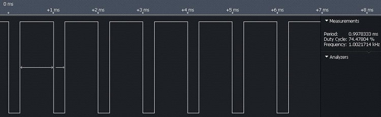 The actual output of the Software PWM
Like us on Facebook. Follow us on Twitter.
About CCS:
CCS is a leading worldwide supplier of embedded software development tools that enable companies to develop premium products based on Microchip PIC ® MCU and dsPIC ® DSC devices. Complete proven tool chains from CCS include a code optimizing C compiler, application specific hardware platforms and software development kits. CCS' products accelerate development of energy saving industrial automation, wireless and wired communication, automotive, medical device and consumer product applications. Established in 1992, CCS is a Microchip Premier 3rd Party Partner. For more information, please visit http://www.ccsinfo.com.
PIC ® MCU, MPLAB ® IDE, MPLAB ® ICD2, MPLAB ® ICD3 and dsPIC ® are registered trademarks of Microchip Technology Inc. in the U.S. and other countries. | October 21, 2014 Expand to read article below Mark Siegesmund, founder of CCS and creator of the CCS C Compiler for PIC® MCUs, has recently published a new book: Embedded C Programming - Techniques and Applications of C and PIC® MCUs. The intended audience are those without formal training in C or those lacking experience programming a microcontroller. This is an excellent text for Electrical Engineers and others who need to get up to speed on the C language. This book provides a hands-on introductory course on concepts of C programming using a PIC® microcontroller and the CCS C compiler. Through a project-based approach, this book provides an easy to understand method of learning the correct and efficient practices to program a PIC® microcontroller in the C language. Principles of C programming are introduced gradually, building on skill sets and knowledge. Early chapters emphasize the understanding of C language through experience and exercises, while the latter half of the book covers the PIC® microcontroller, its peripherals, and how to use those peripherals from within C in great detail.
This book demonstrates the programming methodology and tools used by most professionals in embedded design. The reader will be able to apply what they learn to real-life embedded applications. Providing a step-by-step guide to the subject matter, this book will encourage you to alter, expand, and customize code for use in your own projects.
Key features include:
- A complete introduction to C programming using PIC® microcontrollers, with a focus on real-world applications, programming methodology and tools
- Each chapter includes code examples, exercises and a quiz.
- C code project examples, tables, graphs, charts, references, photographs, schematic diagrams, flow charts and compiler compatibility notes to channel your knowledge into real-world examples.
- Includes Single-Chip C compiler software with full documentation.
- Online educator materials available from publisher.
- Low-cost companion hardware available.
To Purchase or For More Information from Amazon
About the Author:
Mark Siegesmund is a software engineer with over 30 years of experience in embedded sytems within the military, industrial and commercial sectors. He is the founder of Custom Computer Services, Inc. (CCS). CCS specializes in embedded software and hardware, offering development tools for Microchip MCUs and DSCs, as well as a line of embedded Ethernet development tools EZ Web Lynx.
Like us on Facebook. Follow us on Twitter.
About CCS:
CCS is a leading worldwide supplier of embedded software development tools that enable companies to develop premium products based on Microchip PIC ® MCU and dsPIC ® DSC devices. Complete proven tool chains from CCS include a code optimizing C compiler, application specific hardware platforms and software development kits. CCS' products accelerate development of energy saving industrial automation, wireless and wired communication, automotive, medical device and consumer product applications. Established in 1992, CCS is a Microchip Premier 3rd Party Partner. For more information, please visit http://www.ccsinfo.com.
PIC ® MCU, MPLAB ® IDE, MPLAB ® ICD2, MPLAB ® ICD3 and dsPIC ® are registered trademarks of Microchip Technology Inc. in the U.S. and other countries. | October 21, 2014 Expand to read article below CCS has recently added a Project History tool to the C-Aware IDE for PIC® MCUs. This new tool provides a simple UI ideal for: tracking file changes, additions to a project, comparing files, and managing file history - automatically saved by the IDE. Project History is accessible from the 'View' ribbon, under 'Project', within in the IDE.
Selecting Files, Creating Copies, and Deleting Copies.
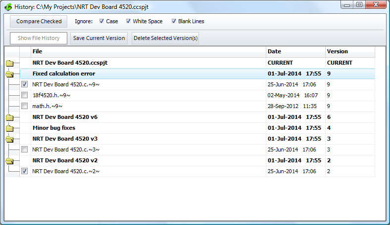
In the Project History tool, by expanding a project version, it displays all of the saved files in that version. Selecting files for comparison, or viewing individual file histories, can be accomplished from here. Clicking the 'Save Current Version' button makes a copy of all current project files and adds it to the version list. These newly copied versions cannot be overwritten by the IDE's History option. The copies can only be deleted through the Project History tool by selecting these versions and clicking the 'Delete Selected Versions' button.
Changing the name of a Project
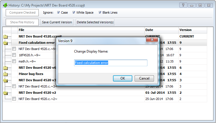
To change the name of a project version, through the Project History tool, double-click on the version name from the list of projects. This will bring up a dialog to change the name in the textfield. By clicking 'OK' the new name is displayed in the list of projects for easier identification of your saved project versions.
Viewing Autosaved Files and Locking or Unlocking Files.
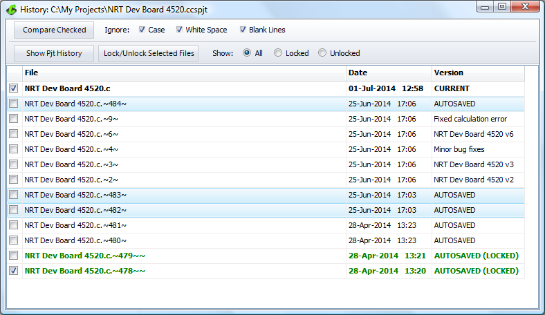
By default the IDE is set up to automatically keep history of files edited within the editor. The new Project History tool allows for viewing these 'autosaved' files. To do this, simply select a file and click the 'Show File History' button. Now all versions of the selected file, that were automatically saved, will be viewable. Also viewable are the project history versions saved by manually saving the project.
Now, through the Project History tool, there is the ability to 'Lock' or 'Unlock' files that were automatically saved. Locking files prevents them from being overwritten when auto-save takes place. The 'Auto-Save' feature can be managed in the 'History' section of 'IDE Options'. Here the maximum number of files saved when auto-saving can be set as well. Once the IDE reaches the maximum number of files saved, older versions will be overwrited - unless they are locked.
Show File History
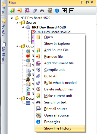 | 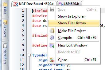 |
Project History has been integrated into the File Tab menu and the Left Navigation panel. Simply right-click on the File Tab, or right-click on the file in the Navigation Panel. This right-click menu will present an option to 'Show File History'. From here the ' AUTOSAVED' files and ability to 'Lock' and 'Unlock' selected files will be made available.
Easily Compare File Versions
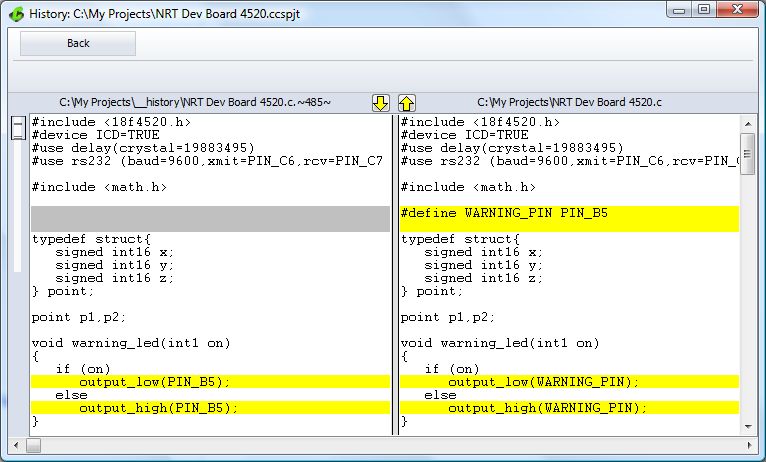
The file compare tool has been built into Project History for quick and simple comparing of file versions. You can compare file versions by checking the boxes next to the two files and clicking 'Compare Checked'. This allows you to see exactly what has changed between the two versions without having to leave the tool!
Give it a try today!
Like us on Facebook. Follow us on Twitter.
About CCS:
CCS is a leading worldwide supplier of embedded software development tools that enable companies to develop premium products based on Microchip PIC ® MCU and dsPIC ® DSC devices. Complete proven tool chains from CCS include a code optimizing C compiler, application specific hardware platforms and software development kits. CCS' products accelerate development of energy saving industrial automation, wireless and wired communication, automotive, medical device and consumer product applications. Established in 1992, CCS is a Microchip Premier 3rd Party Partner. For more information, please visit http://www.ccsinfo.com.
PIC ® MCU, MPLAB ® IDE, MPLAB ® ICD2, MPLAB ® ICD3 and dsPIC ® are registered trademarks of Microchip Technology Inc. in the U.S. and other countries. |
|


