May 13, 2020  Expand to read article below Expand to read article belowThe CCS C Compiler supports the new PIC18FxxQ10 family of microcontroller, which are low-cost alternative to similar general purpose devices.
The PIC18FxxQ10 family come in 28, 40 and 44 pin packages of which up to 36 of them can be used as I/O pins. Additionally has up to 128 K Bytes, 65536 instructions, of Program Flash Memory, up to 1024 Bytes of Data EEPROM and up to 3615 Bytes of Data SRAM.
The PIC18FxxQ10 family has a wide array of Analog and Digital peripherals that can be used with it including:
* 10-bit ADC with Computation module on up to 35 external channels
* 5-bit DAC, two High-Speed Analog Comparators
* Up to 7 Timers (3 8-bit/4 16-bit)
* Windowed Watchdog Timer, a Cyclic Redundancy Check (CRC) module
* Two Capture/Compare/PWM (CCP) modules
* Two 10-bit PWM modules
* Zero-Cross Detect (ZCD) module
* Up to one Complementary Waveform Generator (CWG) module
* Up to eight Configurable Logic Cell (CLC) modules
* Low Voltage Detect (LVD) module
* Up to two Enhanced Universal Synchronous Asynchronous Receiver Transmitter (EUSART) modules
* Up to two Master Synchronous Serial Port (MSSP) modules
Additionally almost every I/O pins for the PIC18FxxQ10 family can be assigned to almost any peripheral, using the CCS C Compiler's #pin_select directive, making it highly configurable for your specific hardware implementation.
If you plan to use this family of devices, make sure you have the latest compiler. Check the status of
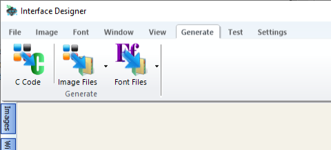
your download rights on our website: www.ccsinfo.com/renewals | August 29, 2019 Expand to read article below CCS has added some new features to the Interface Designer program. The first new feature includes two new buttons added to the 'Generate' tab, and can be used for generating image and font files. These files are structured so that the data contained in them can be directly passed to the gfx_graphics.c driver's gfx_Loadimage() and gfx_Loadfont() functions. This is useful if a different method for loading images and fonts to the hardware is being used, for example, a USB Flash drive.
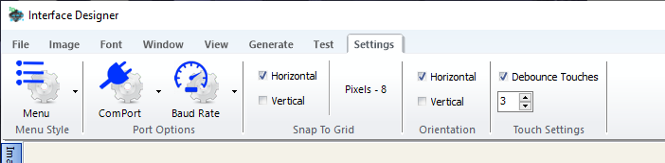
Another new feature that was added to Interface Designer is an option on the Settings tab to enable touch debouncing to the C Code generated by Interface Designer. When 'Debounce Touches' is checked, the code that is generated by Interface Designer requires that the area being pressed must be read the specified number of times in a row to be considered a valid touch. This keeps a momentary bad position read by the touch hardware from causing unexpected code execution.
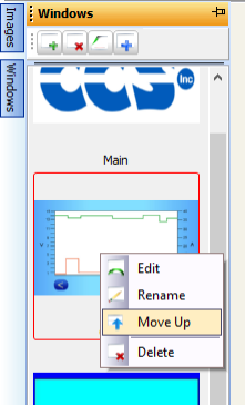
Another new feature added to Interface Designer is a way to reorder the window positions on the windows slide out tray. This is useful because the window that is in the top position of the windows slide out tray is the window that is displayed on power up by the code generated by Interface Designer. This is done by selecting a window in the windows slide out panel, right-clicking the mouse button and selecting 'Move Up'. This will move the selected window up one position. An example of a case were this may be used is if a new splash screen needs to be displayed on power up of an existing project. With this added feature, all that needs to be done to add the new splash screen is to add the image to the project, create a new window and add the image to it, use the 'Move Up' feature to move the new window to the top position, re-generate the library C Code, build and reprogram the display board and download the new image to the display board.
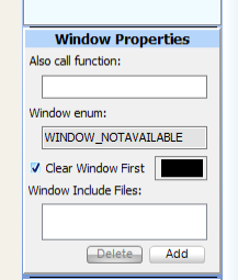
Another new feature added to Interface Designer is an option to clear the display with a solid color before the images for a window are drawn. This is enabled by checking the 'Clear Window First' check box on the 'Window Properties' box on the window images slide out panel. Then you can select the desired color from the color picker box next to it. This is useful in cases where the images added to a window are smaller then then the window and a uniform background color is desired.
The last new feature that was added to Interface Designer are X and Y coordinates that the user's mouse cursor is at when over an image or window. This feature can be seen in the bottom left hand corner of the status panel. This was added to aid in adding areas to images.

Like us on Facebook. Follow us on Twitter.
About CCS:
CCS is a leading worldwide supplier of embedded software development tools that enable companies to develop premium products based on Microchip PIC ® MCU and dsPIC ® DSC devices. Complete proven tool chains from CCS include a code optimizing C compiler, application specific hardware platforms and software development kits. CCS' products accelerate development of energy saving industrial automation, wireless and wired communication, automotive, medical device and consumer product applications. Established in 1992, CCS is a Microchip Premier 3rd Party Partner. For more information, please visit http://www.ccsinfo.com.
PIC ® MCU, MPLAB ® IDE, MPLAB ® ICD2, MPLAB ® ICD3 and dsPIC ® are registered trademarks of Microchip Technology Inc. in the U.S. and other countries. | August 29, 2019 Expand to read article below CCS has added an new driver, pr9200.c, for communication with a Phychips RED5 UHF RFID reader module. The RED5 is a hybrid module which integrates a Phychips PR9200 high performance UHF RFID reader chipset, TCXO, Balun, Coupler, Saw filter, Power amp and low pass filter. The driver contains all the necessary functions and settings to communicate with the RED5 module to detect, read and write ISO-18000-6C EPC Gen 2 UHF RFID tags.
The driver communicates with the RED5 module via a UART connection, and has defines for selecting the pins to use for the communication along with options. It includes selecting whether to use the PIC® MCU hardware CRC peripheral or a software CRC for doing the CRC16 for messages sent to and received from the RED5 module. The driver contains functions for getting or setting every parameter the RED5 module has, for example, getting and setting the Region, TX Power Level, Session, Frequency Hopping Table, etc., as well as functions for detecting, reading and writing UHF RFID tags. Additionally, almost every function has the option of being cooperative or waiting for a response. For some functions, like setting the TX Power Level, it may be okay to call the function and wait for a response. However in some cases, doing a tag detection, which, depending on the parameter passed to it, can take multiple seconds to finish, it may be preferred to start the process and then return so the PIC can execute other code while waiting for the RED5 module to respond and process those responses as they are received.
CCS's new pr9200.c driver for communicating with a Phychips RED5 mode has all the necessary functionality to get your UHF RFID project started easily and quickly.
Like us on Facebook. Follow us on Twitter.
About CCS:
CCS is a leading worldwide supplier of embedded software development tools that enable companies to develop premium products based on Microchip PIC® MCU and dsPIC® DSC devices. Complete proven tool chains from CCS include a code optimizing C compiler, application specific hardware platforms and software development kits. CCS' products accelerate development of energy saving industrial automation, wireless and wired communication, automotive, medical device and consumer product applications. Established in 1992, CCS is a Microchip Premier 3rd Party Partner. For more information, please visit http://www.ccsinfo.com.
PIC® MCU, MPLAB® IDE, MPLAB® ICD2, MPLAB® ICD3 and dsPIC® are registered trademarks of Microchip Technology Inc. in the U.S. and other countries. | August 29, 2019 Expand to read article below The CCS C Compiler has added three new functions to the #use spi() library when setup as an SPI master for transferring data to and from a SPI slave device. The functions are the spi_transfer(), spi_transfer_out() and spi_transfer_in() functions. These functions are available for all devices when setup as a SPI master using the hardware SSPx or SPIx peripherals or when doing a software SPI. One advantage of using the spi_transfer() functions is that all the steps for reading or writing data to and from an SPI slave device can be done in a single call to one of the functions instead of multiple calls to the spi_xfer() function. Additionally, if an enable pin is specified in #use spi(), it will set the enable pin to the active state at the start of the transfer, transfer all the bytes, and then set the enable pin to the inactive state at the end of the transfer, instead of toggling the enable pin between the active and inactive states between each call to spi_xfer().
The spi_transfer_out() function transfers data to a slave device and is used as follows:
spi_transfer_out(wData, Count);
The above will cause the master to set the enable pin to the active state, if the enable pin was specified. It will then write count bytes to the slave, and set the enable pin to the inactive state, if enable pin was specified.
The spi_transfer_in() function transfers data from a slave device and is used as follows:
spi_transfer_in(rData, Count);
The above will cause the master to set the enable pin to the active state, if enable pin was specified, read count bytes from slave, and set the enable pin to the inactive state, if enable pin was specified. When using the spi_transfer_in() function it will output a low on the SPI DO pin while the data is being clocked in from the slave device.
The spi_transfer() function simultaneously transfers data to and from a slave device and is used as follows:
spi_transfer(wData, rData, Count);
The above will cause the master to set the enable pin to the active state, if enable pin was specified, write and read count bytes to and from the slave, and set the enable pin to the inactive state, if enable pin was specified.
See 9356.c in the Drivers folder where the CCS C compiler was installed for an example showing how to use the spi_transfer() function. The 9356.c driver is for a Microchip 93C56 Serial EEPROM with 2K bits of memory.
Additionally for devices that have a Direct Memory Access (DMA) peripheral, #use spi() has been updated so that DMA can be used with the spi_transfer() functions when using the hardware SSPx or SPIx peripheral to transfer data to and from SSPx or SPIx peripheral. Using the option USE_DMA in #use spi() will enable using DMA for the spi_transfer() functions, and the options DMA_RX_CHANNEL and DMA_TX_CHANNEL can be used in #use spi() to set the DMA RX and TX channels to something other then the default channels. By default the library uses DMA channel 0 to receive data and DMA channel 1 to transmit data in the PCD compiler. In the PCH compiler, the library uses DMA channel 1 to receive data and DMA channel 2 to transmit data.
When DMA is used, the spi_transfer() functions will not stop code execution while waiting for the spi_transfer() functions to finish the transfer. This is an advantage because it allows the PIC to execute other code while the DMA and SPI peripherals are transferring data to and from the SPI slave. To determine when the SPI transfer has been completed, the function spi_transfer_done() was add to the #use spi() library. Additionally the spi_transfer_clear() was also added the the #use spi() library to clear the interrupt flag used to determine when the transfer is complete. These functions check and clear the interrupt flag for the DMA channel used for receiving from the SPI peripheral. The PCD compiler uses the DMAx interrupt flag and the PCH compiler uses the DMAxDCNT interrupt flag.
When using the USE_DMA option the enable=PIN_xx option is not supported, by the #use spi() library, except for device that have a hardware SSxOUT pin and the device is set up to use the hardware enable pin. In that case, the spi_transfer() function will control the enable pin when the USE_DMA option is used. A PIC18F47K42 is an example of the PIC ® that has a hardware controllable enable pin for the SPI peripheral.
Like us on Facebook. Follow us on Twitter.
About CCS:
CCS is a leading worldwide supplier of embedded software development tools that enable companies to develop premium products based on Microchip PIC ® MCU and dsPIC ® DSC devices. Complete proven tool chains from CCS include a code optimizing C compiler, application specific hardware platforms and software development kits. CCS' products accelerate development of energy saving industrial automation, wireless and wired communication, automotive, medical device and consumer product applications. Established in 1992, CCS is a Microchip Premier 3rd Party Partner. For more information, please visit http://www.ccsinfo.com.
PIC ® MCU, MPLAB ® IDE, MPLAB ® ICD2, MPLAB ® ICD3 and dsPIC ® are registered trademarks of Microchip Technology Inc. in the U.S. and other countries. | May 6, 2019 Expand to read article below The CCS C Compiler now supports the dsPIC33CH family of devices! The dsPIC33CH family are the first dual core PIC®MCUs available from Microchip, which allows the user to run two independent programs on the same device. Additionally each core has separate clock circuits allowing each core to run different clock frequencies, with the Master core's max frequency being 180MHz (90 MIPS) and the Slave core's max frequency being 200MHz (100 MIPS).
Currently devices are available with the Master core having up to 512 Kbytes of flash program memory and up to 48 Kbytes of data RAM, and the Slave core having up to 72 Kbytes of Program RAM (PRAM) and 16 Kbytes of data RAM. Since the Slave core's program memory is PRAM, its actual program is stored in the Master core's Flash program memory and loaded at run time by the Master core into the Slave core's PRAM. The CCS C Compiler provides the functions load_slave_program() and verify_slave_program() for loading and verifying the Slave core's PRAM. See ex_ch_master.c and ex_ch_slave.c for an example of how to build and load a Slave core's program. Additionally, since the Master core and Slave core have separate data RAM, Microchip provides two methods for the cores to communicate with each other. The first method is a series of Mailbox registers, whose direction and protocol can be programmed with configuration fuses to communicate between the cores. The second method is dedicated to read and write FIFO registers that can be used to communicate between the cores. Both are part of the Master Slave Interface (MSI) peripheral and the CCS C Compiler provides several functions for setting it up, checking the status, as well as reading and writing data to and from the mailbox and FIFO registers.
Some features of the dsPIC33CH family are as follows; the Master core has one 16-bit Timer, six DMA channels, eight SCCP peripherals, two UART peripherals, two SPI peripherals, two I2C peripherals, up to two CAN FD peripherals, two SENT peripherals, one CRC peripheral, one QEI peripheral, four CLC peripherals, four 16-bit High-Seed PWM peripherals, a 12-bit ADC with up to 16 channels, and one 12-bit DAC with Analog comparator peripheral. The Slave core has one 16-bit Timer, two DMA channels, four SCCP peripherals, one UART peripheral, one SPI peripheral, one I2C peripheral, one QEI peripheral, four CLC peripherals, eight 16-bit High-Speed PWM peripherals, a 12-bit ADC with two dedicated ADC cores and one shared ADC core with up to 18 channels, and three 12-bit DAC with Analog comparator peripherals.
The SCCP peripheral is newly combined Input Capture, Output Compare, PWM and 32-bit Timer peripherals. This peripheral can be used as either 2 16-bit Timers or a singular 32-bit Timer, a 16-bit or 32-bit Output Compare, a 16-bit or 32-bit Input Capture, or a 16 PWM. Support has been added to #use pwm() for PCD devices that have SCCP peripherals.
Like us on Facebook. Follow us on Twitter.
About CCS:
CCS is a leading worldwide supplier of embedded software development tools that enable companies to develop premium products based on Microchip PIC® MCU and dsPIC® DSC devices. Complete proven tool chains from CCS include a code optimizing C compiler, application specific hardware platforms and software development kits. CCS' products accelerate development of energy saving industrial automation, wireless and wired communication, automotive, medical device and consumer product applications. Established in 1992, CCS is a Microchip Premier 3rd Party Partner. For more information, please visit http://www.ccsinfo.com.
PIC® MCU, MPLAB® IDE, MPLAB® ICD2, MPLAB® ICD3 and dsPIC® are registered trademarks of Microchip Technology Inc. in the U.S. and other countries. | May 6, 2019 Expand to read article below The CCS C Compiler has added three new functions to the #use i2c() library when setup as an I2C master for transferring data to and from an I2C slave device, the functions are the i2c_transfer(), i2c_transfer_out() and i2c_transfer_in() functions. These functions are added to the CCS C Compiler to support some new devices whose I2C peripheral is not compatible with the legacy i2c_start(), i2c_write(), i2c_read() and i2c_stop() functions. However, these functions are available for all devices when setup as an I2C master using the hardware peripheral or doing a software I2C. Because these functions are supported on all devices, CCS recommends using them instead of the legacy functions for developing code making the code portable to all devices. Another advantage to using these functions, compared to the legacy functions, is that they perform all the I2C steps in a single function call instead of multiple function calls.
The i2c_transfer_out() function transfers data to a slave device use the following:
ack = i2c_transfer_out(SlaveAddr, wData, Count);
The above causes the master to perform an I2C start, send a write command to the specified slave address, send count bytes to slave, perform an I2C stop and return the acknowledge bit. If the acknowledge bit is an ACK, then the transfer is successful. If at any time the slave device NACKs any of the data bytes, the i2c_trasnfer_out() function immediately performs an I2C stop and return a NACK indicating the transfer was unsuccessful.
The i2c_transfer_in() function transfers data from a slave device as follows:
ack = i2c_transfer_in(SlaveAddr, rData, Count);
The above causes the master to perform an I2C start, send a read command to the specified slave address, read count bytes from slave, perform and I2C stop and return the acknowledge bit. If the acknowledge bit is an ACK, then the transfer is successful. When reading data from the a slave device the only byte of data that the slave acknowledges is the read command. If the slave NACKs the read command the i2c_transfer_in() function immediately performs an I2C stop and return a NACK indicating the transfer was unsuccessful.
The i2c_transfer() function is a combination of both the i2c_transfer_out() and i2c_transfer_in() functions, used to transfer data to a slave device or transfer data to and from a slave device. If used to transfer data to a slave device, it works the same as the i2c_transfer_out() function.
When transferring data to and from a slave device, use the following:
ack = i2c_transfer(SlaveAddr, wData, wCount, rData, rCount);
The above causes the master to perform an I2C start, send a write command to the specified slave address, send count bytes to slave, perform an I2C restart, send a read command to the specified slave address, read count bytes from slave, perform and I2C stop and return the acknowledge bit. If the acknowledge bit is an ACK, then the transfer is successful. As with the i2c_transfer_out() and i2c_transfer_in() function, if the slave NACKs any of the bytes being transferred to it the i2c_transfer() function immediately performs an I2C stop and return a NACK indicating the transfer was unsuccessful.
See 241025.c and ds1631.c in the Drivers folder where the CCS C compiler is installed for a couple examples showing how to use the i2c_transfer() function. The 241025.c driver is for a Microchip 24XX1025 I2C Serial EEPROM with 1024K bits of memory, and the ds1631.c driver is Dallas 1631 I2C temperature sensor.
Like us on Facebook. Follow us on Twitter.
About CCS:
CCS is a leading worldwide supplier of embedded software development tools that enable companies to develop premium products based on Microchip PIC ® MCU and dsPIC ® DSC devices. Complete proven tool chains from CCS include a code optimizing C compiler, application specific hardware platforms and software development kits. CCS' products accelerate development of energy saving industrial automation, wireless and wired communication, automotive, medical device and consumer product applications. Established in 1992, CCS is a Microchip Premier 3rd Party Partner. For more information, please visit http://www.ccsinfo.com.
PIC ® MCU, MPLAB ® IDE, MPLAB ® ICD2, MPLAB ® ICD3 and dsPIC ® are registered trademarks of Microchip Technology Inc. in the U.S. and other countries. | June 15, 2017 Expand to read article below Many newer Microchip PIC® microcontrollers have re-programmable peripheral pins (RP). These pins allow the user to dynamically allocate peripherals to these pins, such as external interrupts, input capture, PWM, serial, timers and more. This offers the designer great flexibility when designing a product since the functionality of these pins can be changed at run-time. The data sheet for a device will list he pin assignments and these pins are denoted as either RPxx or RPIxx, where xx is the RP pin number. Pins that are RPIxx can only be programmed as an input (timer input, serial input, interrupt input, etc), whereas RPxx pins can be programmed either as an input or output (PWM output, serial output, etc). PIC® MCUs that have this feature can be configured in the CCS C Compiler using the pin_select preprocessor and function.
The first method for assigning I/O pins to a peripheral is the #pin_select directive. The #pin_select directive is a preprocessor directive for assigning I/O pins to peripherals and is executed before main() starts. The syntax for this command is as follows: #pin_select function=pin
A list of functions and pins that can be used with the #pin_select directive is located in the device's header file near the top of the file, opening the device's header file and searching for #pin_select is the quickest way to find them. The following is an example of how to assign pins to the UART1 RX and TX pins:
#pin_select U1TX=PIN_C6
#pin_select U1RX=PIN_C7
When using RP pins with a peripheral library, such as #use rs232(), the #pin_select must come before the #use directive, for example:
#pin_select U1TX=PIN_C6
#pin_select U1RX=PIN_C7
#use rs232(UART1, baud=9600, stream=U1)
In addition to #pin_select the CCS C Compiler also provides the pin_select() function for assigning pins to a peripheral. The pin_select() function can be used to assign, reassign and unassign pins to/from a peripheral at run-time. This allows the flexibility of using the same pin for multiple peripherals or using pins as both peripheral pins and I/O pins. The pin_select() function uses the following syntax: pin_select("function", pin);. The functions and pins are the same as what is used with the #pin_select directive, the only difference being that the function is passed as a constant string. The following is an example of how to assign pins to the UART1 peripheral:
pin_select("U1TX", PIN_C6);
pin_select("U1RX", PIN_C7);
To unassign a pin from a peripheral depends on whether it an input peripheral or an output peripheral. To unassign a pin from an output peripheral is done as follows:
pin_select("NULL", PIN_C6); //unassign PIN_C6 from output peripheral.
To unassign a pin from an input peripheral is done as follows:
pin_select("U1RX", FALSE); //unassign pin from U1RX input peripheral.
Because of how output peripherals are assigned to RP pins it is possible to assign multiple pins to the same output peripheral when using the pin_select() directive. For example the following will assign multiple pins to the CCP1 peripheral:
pin_select("CCP1OUT", PIN_B0);
pin_select("CCP1OUT", PIN_B1);
This method of tying several pins to the same output can only be performed with the pin_select() function, #pin_select cannot be used to do this.
Like us on Facebook. Follow us on Twitter.
About CCS:
CCS is a leading worldwide supplier of embedded software development tools that enable companies to develop premium products based on Microchip PIC ® MCU and dsPIC ® DSC devices. Complete proven tool chains from CCS include a code optimizing C compiler, application specific hardware platforms and software development kits. CCS' products accelerate development of energy saving industrial automation, wireless and wired communication, automotive, medical device and consumer product applications. Established in 1992, CCS is a Microchip Premier 3rd Party Partner. For more information, please visit http://www.ccsinfo.com.
PIC ® MCU, MPLAB ® IDE, MPLAB ® ICD2, MPLAB ® ICD3 and dsPIC ® are registered trademarks of Microchip Technology Inc. in the U.S. and other countries. | June 15, 2017 Expand to read article below Most embedded microprocessors and microcontrollers, including the Microchip PIC® MCU families, do not contain a hardware implemented floating-point calculator. This means that all float calculations must be implemented in software using integer arithmetic, which is very resource intensive. In turn, performance heavy applications and resource limited platforms may be unable to utilize floating point numbers in their implementation. The solution for this is to instead use fixed-point arithmetic, which is simplified by the CCS C Compiler's fixed type feature.
Fixed-point arithmetic is an implementation that uses a scaling factor to represent decimal numbers in integer form. The CCS C Compiler implements this using 16 or 32 bit integers and a scaling factor of 10-n. A fixed type can be declared as follows:
int16 _fixed(n) foo; where 0 < n < 6
int32 _fixed(n) foo; where 0 < n < 11
The value n determines the number of decimal places of accuracy the variable will contain, as well as the maximum representable value. Since n is part of the type and determines what instructions are generated, it must be given as a constant at compile time.
For int16 _fixed(2) : Max = 65,535 * 10-2 = 655.35
For int32 _fixed(5) : Max = 4,294,967,295 10-5 = 42,949.67295
The binary/hexadecimal representation for any number can then be determined by multiplying by the inverse of the scaling factor and converting.
237.16 * 10-2 = 23716 = 0x5CA4
The fixed type is compatible with another fixed type of the same n for the 4 basic arithmetic operations. They are not compatible with fixed types with a different n.
int16 _fixed(1) f1 = 5.5;
int16 _fixed(1) f2 = 2.5;
f1 + f2; //evaluates to 8.0
f1 - f2; //evaluates to 3.0
f1 * f2; //evaluates to 13.7
f1 / f2; //evaluates to 2.2
It can also perform arithmetics with literals and cast integers.
int16 _fixed(2) f1 = 22.14;
int16 i1 = 7;
f1 + 19.52; //evaluates to 41.66
f1 - (int16 _fixed(2)) i1; //evaluates to 15.14
The increment and decrement operations function the same in binary. This equates to adding or subtracting 1 times the scaling unit.
int16 _fixed(3) f1= 5.234;
f1++; //f1 = 5.235
Casting a fixed type to an integer will truncate the decimal places. This can also be used to isolate the digits after the decimal by subtracting the integer cast from the original
int16 _fixed(2) f1 = 6.94;
int16 noDec = (int16) f1; //noDec = 6
int16 _fixed(2) decOnly = f1 - noDec; //decOnly = 0.94
The CCS C Compiler also supports using printf, sprintf, etc. with the fixed-point type using the "%w" format flag. It will print the value with no leading zeroes and digits after the decimal equal to the precision.
Code:
int16 _fixed(2) f1 = 1.5;
int16 _fixed(2) f2 = 22.78;
int16 _fixed(3) f3 = 5.21
printf("%w - %w - %w", f1, f2, f3);
Output:
1.50 - 22.78 - 5.210
Floating-point numbers have an inescapable error when representing decimal in which expressions that should evaluate to be equal will be off at a very low decimal point. This happens because some decimal numbers in base10, such as 0.1, cannot be perfectly represented in base2, thus causing a rounding error. This is similar to how 1/3 cannot be represented in base10 and is then rounded to 0.33... to whatever precision is needed. Since the CCS C Compiler's implementation of fixed-point uses a decimal scalar, there is 100% precision in base10. This makes it perfect for handling money and other values where this precision is necessary.
Fixed-point operations yield significant performance increases over floating-point. In order to quantify this, benchmarks were performed using a PIC18F45K22 and the CCS C Compiler. One of the on-chip timers was used to approximate the amount of time an arithmetic operation took. For both floating-point and 16 bit fixed-point at 2 places accuracy, each operation was timed and averaged 50 times on a spread of values. The average times for each could then be compared to generalize performance.
The benchmarking results are as follows:
- Add (+): Fixed ~19.6 times faster than float.
- Subtract (-): Fixed ~19.4 times faster than float.
- Multiply (*): Float ~2.7 times faster than fixed.
- Divide (/): Fixed ~3.3 times faster than float.
The only operation that floating-point performs better is multiplication. This is logical since floats are stored in a multiplicative form (significand x base exponent). However, fixed-point performs better on the other three, particularly on addition and subtraction.
There is also a program memory usage difference between implementing fixed-point and floating-point. The actual number of instructions it takes to implement the arithmetic operations is significantly different for both. The following program was compiled using both options for the PIC18F45K22.
#ifdef USE_FIXED
int16 _fixed(2) a, b, c;
#else
float a, b, c;
#endif
void main() {
a = 2.25;
b = 0.85;
c = a + b;
printf("Add: %w", c);
c = a - b;
printf("Subtract: %w", c);
c = a * b;
printf("Multiply: %w", c);
c = a / b;
printf("Divide: %w", c); }
The compiled program's memory statistics were as follows.
Fixed Option:
- 364 instructions
- 0.84KB ROM usage
- 2.6% ROM usage
Float Option:
- 787 instructions
- 2.03KB ROM usage
- 6.3% ROM usage
Switching from the fixed implementation to float increased the instruction count by over 400. This may or may not be significant on the PIC18F45K22, depending on program complexity. However, at 32KB of ROM, it is on the higher end in terms of program memory. On the more limiting units in the PIC18 family, this would be an extremely significant amount of space.
Like us on Facebook. Follow us on Twitter.
About CCS:
CCS is a leading worldwide supplier of embedded software development tools that enable companies to develop premium products based on Microchip PIC ® MCU and dsPIC ® DSC devices. Complete proven tool chains from CCS include a code optimizing C compiler, application specific hardware platforms and software development kits. CCS' products accelerate development of energy saving industrial automation, wireless and wired communication, automotive, medical device and consumer product applications. Established in 1992, CCS is a Microchip Premier 3rd Party Partner. For more information, please visit http://www.ccsinfo.com.
PIC ® MCU, MPLAB ® IDE, MPLAB ® ICD2, MPLAB ® ICD3 and dsPIC ® are registered trademarks of Microchip Technology Inc. in the U.S. and other countries. | May 26, 2017 Expand to read article below The CCS C Compiler now support the PIC18F24K42 family of devices. Currently available devices have up to 32 KB of Program Flash Memory, 256 B of Data EEPROM and up to 2 KB of Data SRAM. Additionally they have 25 I/O pins, 24 12-bit ADC channels, 1 5-bit DAC, 2 Comparators, 3 8-bit Timers, 3 16-bit Timers, Windowed Watchdog Timer, Signal Measurement Timer (SMT), 4 CCP peripherals, 4 10-bit PWM peripherals, 3 Complementary Waveform Generators (CWG), Numerically Controlled Oscillator (NCO), 4 CLC peripherals, Zero-Cross Detect, 2 UART peripherals, 2 I2C peripherals and 1 SPI peripheral.
Additionally each of the I/O pins can be assigned to almost any peripheral using the CCS C Compiler's #pin_select directive make it highly configurable for your specific hardware implementation. Future devices in this family will have up to 128 KB of Program Flash Memory, up to 1 KB of Data EEPROM, up to 8 KB for Data SRAM, up to 44 I/O pins and up to 43 ADC channels. 8KB of RAM is a significant upgrade for the PIC18 family, as previously the architecture only supported 4KB of RAM.
The newest feature that this family has is an optionally enabled interrupt vector table (IVT). The IVT allows for quicker entry into a peripheral's interrupt service routine (ISR). Normally the compiler has to search through the interrupt enable and interrupt flag bits to determine which peripheral caused the interrupt in order jump to the correct ISR. When the IVT is enabled each interrupt has a specific address it will go to when an interrupt occurs which contains the address of that peripheral's ISR, which makes servicing the ISR faster. The IVT can be enabled for these device in the CCS C Compiler by adding #device vector_ints to the code for this family of devices.
Like us on Facebook. Follow us on Twitter.
About CCS:
CCS is a leading worldwide supplier of embedded software development tools that enable companies to develop premium products based on Microchip PIC® MCU and dsPIC® DSC devices. Complete proven tool chains from CCS include a code optimizing C compiler, application specific hardware platforms and software development kits. CCS' products accelerate development of energy saving industrial automation, wireless and wired communication, automotive, medical device and consumer product applications. Established in 1992, CCS is a Microchip Premier 3rd Party Partner. For more information, please visit http://www.ccsinfo.com.
PIC® MCU, MPLAB® IDE, MPLAB® ICD2, MPLAB® ICD3 and dsPIC® are registered trademarks of Microchip Technology Inc. in the U.S. and other countries. | May 26, 2017 Expand to read article below Reliably sending data between two devices usually involves a checksum. Creating a checksum of data is a great way to detect if data has be successfully received; by comparing a received checksum to a mathematically determined checksum it can be determined if the data was sent and received properly. A common and easy method of performing a checksum is just summing or XORing all the bytes in the data. Unfortunately this method does accurately detect situations where data may have been received correctly. For example, the result of 0 XOR 0 is still 0. That means a checksum based on XOR would couldn't tell the difference between 0x0000 or 0x00.
The Cyclic Redundancy Check (CRC) is a more robust method for hashing data. In reference to the previous example, the CRC of 0x0000 isn't 0x00. Many new PIC® MCUs released today include a CRC module that perform this algorithm quickly in hardware, and CCS provides a library for accessing this module.
There are two basic versions of the CRC module that some Microchip PIC® MCUs have, a 16-bit module and a 32-bit module. The following getenv() statement can be used in the CCS C Compiler to determine if the device has a CRC module:
getenv("CRC") //will return 1 if it device has a HW CRC module
Both version of the CRC module has a programmable polynomial CRC equation, for the 16-bit modules the polynomial can be up to 16 bits wide and for the 32-bit modules the polynomial can be up to 32 bits wide. The setup_crc() function can be used in the CCS C Compiler for setting up the CRC polynomial. For example the following will setup the CRC module to generate a checksum using the CRC-16 CCITT polynomial, x^16 + x^12 + X^5 + 1:
setup_crc(16, 12, 5, 0);
To calculate the CRC checksum the CCS C Compiler supplies the following functions, crc_calc8(), crc_calc16 and crc_calc32(), for devices with a 32-bit CRC module only. The function that should be used depends on the polynomial size that was set with the setup_crc() function. For polynomials that are 8-bits or less the crc_calc8() function should be used, for polynomials that are greater then 8-bits and 16-bits or less the crc_calc16() function should be used and for polynomials that are greater then 16-bits and 32-bits or less the crc_calc32() function should be used. Additionally the crc_calc8(), crc_calc16() and crc_calc32() have an optional parameter that allows setting the width of the data that the CRC checksum is being calculated for, the data width defaults to the width the function, 8-bits for crc_calc8(), 16-bits for crc_calc16() and 32-bits for crc_calc32(). Finally the CCS C Compiler supplies that crc_init() function that is used to set the initialization value of the CRC generator. This function should be called before every call to one of the CRC calculation function to guarantee correct results.
The following is an example of using the CRC module to generate a 16-bit CRC for some 8-bit data that will be transmitted with the UART peripheral:
#use rs232(UART1, baud=9600, errors)
#define START 0x01
#define END 0x0D
void tx_data(unsigned int8 *Data, unsigned int8 Length)
{
unsigned int16 CRC;
crc_init(0);
CRC = crc_calc16(Data, Length, 8);
putc(START);
printf("%s%04LX", Data, CRC);
putc(END);
}
void main(void)
{
unsigned int8 Data[32];
unsigned int8 Length;
unsigned int16 Count = 0;
setup_crc(16, 12, 5, 0);
while(TRUE)
{
Length = sprintf(Data, "Count=%lu,", Count++);
tx_data(Data, Length);
delay_ms(100); } }
Like us on Facebook. Follow us on Twitter.
About CCS:
CCS is a leading worldwide supplier of embedded software development tools that enable companies to develop premium products based on Microchip PIC ® MCU and dsPIC ® DSC devices. Complete proven tool chains from CCS include a code optimizing C compiler, application specific hardware platforms and software development kits. CCS' products accelerate development of energy saving industrial automation, wireless and wired communication, automotive, medical device and consumer product applications. Established in 1992, CCS is a Microchip Premier 3rd Party Partner. For more information, please visit http://www.ccsinfo.com.
PIC ® MCU, MPLAB ® IDE, MPLAB ® ICD2, MPLAB ® ICD3 and dsPIC ® are registered trademarks of Microchip Technology Inc. in the U.S. and other countries. |
|


