May 13, 2020  Expand to read article below Expand to read article belowThe CCS C Compiler supports the new PIC18FxxQ10 family of microcontroller, which are low-cost alternative to similar general purpose devices.
The PIC18FxxQ10 family come in 28, 40 and 44 pin packages of which up to 36 of them can be used as I/O pins. Additionally has up to 128 K Bytes, 65536 instructions, of Program Flash Memory, up to 1024 Bytes of Data EEPROM and up to 3615 Bytes of Data SRAM.
The PIC18FxxQ10 family has a wide array of Analog and Digital peripherals that can be used with it including:
* 10-bit ADC with Computation module on up to 35 external channels
* 5-bit DAC, two High-Speed Analog Comparators
* Up to 7 Timers (3 8-bit/4 16-bit)
* Windowed Watchdog Timer, a Cyclic Redundancy Check (CRC) module
* Two Capture/Compare/PWM (CCP) modules
* Two 10-bit PWM modules
* Zero-Cross Detect (ZCD) module
* Up to one Complementary Waveform Generator (CWG) module
* Up to eight Configurable Logic Cell (CLC) modules
* Low Voltage Detect (LVD) module
* Up to two Enhanced Universal Synchronous Asynchronous Receiver Transmitter (EUSART) modules
* Up to two Master Synchronous Serial Port (MSSP) modules
Additionally almost every I/O pins for the PIC18FxxQ10 family can be assigned to almost any peripheral, using the CCS C Compiler's #pin_select directive, making it highly configurable for your specific hardware implementation.
If you plan to use this family of devices, make sure you have the latest compiler. Check the status of
your download rights on our website: www.ccsinfo.com/renewals | May 13, 2020 Expand to read article below Have fun learning about embedded programming with the CCS Robot Car development kit. The development kit includes the prototyping board to attach to the robot car once it is assembled. The sensors provided as part of the assembly will be used directly in the example programs from the Exercise Book and to be able to compete autonomously.
Infrared sensors can detect white or dark under the car and can be used for line sensing or line following. Proximity sensors can detect if it is approaching an object. Magnetic compass can be used to detect current heading. The car is controlled by two direct DC motors. This kit is a great learning tool for showing how an embedded system can read analog and digital sensors, then react to those sensors.
This kit has an optional EZ App Lynx connector. If an EZ App Lynx is attached, the car can be controlled over Bluetooth® using an Android or Apple iOS device. All sensor readings can be displayed on the Android or Apple iOS device.
CCS designed a Robot Soccer field for Maker Faire. Kids, and adults, enjoyed playing Robot soccer with tablets. See a video here: https://www.ccsinfo.com/content.php?page=video_tutorials
Robot Car Development Kit is available Now! | May 13, 2020 Expand to read article below Introducing support added for debugging dsPIC33CH devices for both the master and slave cores to the CCS C Compiler and IDE using the CCS ICD-U80 or ICD-U64 device programmers. This support will be available starting with Compiler version 5.094 and ICD firmware version 3.42 and newer. In addition to debugging the slave core with the CCS tools the slave core can also be programmed starting with the previously mentioned version. Both of these features will aid in developing code for the dsPIC33CH dual core devices.
When debugging there are three setups that can be done. First debug only the master core, second debug only the slave core, or third debug both the master and slave core at the same time. When debugging the slave core the master core's configuration bit need to be set so that the slave core can be debugged. At minimum the S1_ISOLAT, S1_DEBUG and S1_ICSPx, x being the debug pin to use for the slave core, should be set. The S1_ISOLAT configuration fuse allows the slave core to operate even if the master core hasn't set the SLVEN bit in the MSI1CON register, enabling the slave core to run, the S1_DEBUG configuration fuse enables the slave core debugger and the S1_ICSPx configuration fuses sets which S1MCLRx, S1PGCx and S1PGDx pins are being used to debug the slave core.
When debugging both the master core and slave core at the same time it requires that two instances of the CCS C Compiler and IDE be running, two device programmers, and the development board will have to have two ICD connectors on it connected to different MCLR, PGC and PGD pins, one for the master core and one for the slave core. To run two instances of the CCS C Compiler and IDE +FORCE_NEW needs added to the target line of the icon used to launch the IDE, for example:
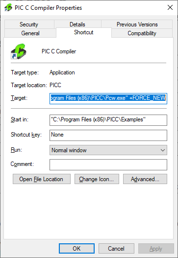
With the above change when using that icon to start the IDE will cause a new instance of the IDE to start allowing for more the one instance to be running. Once there are two instances of the IDE running the master core project should being opened in one and the salve core project should be opened in the other. Next starting with the master core project, build it with the appropriate slave core configuration fuses set and start the debugger. Assuming both ICDs are connected to the PC a selection box similar to the following should pop up:
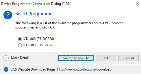
Select the ICD that is connected to the master core's programming/debugging pins and select 'OK'. If you're not sure which ICD is connected to the master core you may want to disconnect the ICD connect to the slave core debugging pins from the PC and then start the master core's debugger, then when the master core's debugger is loaded the slave core ICD can be reconnected to the PC. Once the master code program debugger is loaded, switch to the CCS IDE instance with the slave core project, build it and start its debugger. Once it's done loading both the master and slave core can be debugged at the same time.
One thing to be aware of the master code debugger using the MCLR pin of the PIC. If the master core's debugger pulls that pin low to reset the master core it will also reset the slave core. So if the master core debugger is reset or the program if reloaded when the slave core is also being debugged, the slave core's debugger needs to be reset to synchronize it with the slave core. | May 13, 2020 Expand to read article below During this time of global uncertainty and change, we want to assure you that we are taking every precaution to ensure that we can safely support our customers during this time.
Despite these challenges, CCS staff is continuing to provide technical support, as well as processing orders. It is essential customers have the tools they need to provide the development of existing or new products that may be necessary in the fight of Covid-19.
Many of our existing customers are having to work from home and we want to remind everyone of our Software Licensing Agreement. We pre-register all compilers in a user's name. You can install your compiler on your home PC and laptops. If you do not have access to the registration files and installer, contact customer service for assistance.

CCS wants to help further embedded development by customers, and is offering a discount on any new compilers or maintenance plan purchases. The customers that need development boards, and programmers, we are offering Free Ground shipping (to the U.S.48) so you can get the tools you need to continue working from home.
Most importantly, as we work together in this unique and rapidly changing environment, we do so with confidence that we will overcome this challenge. Until then, we hold our enduring commitment to the health and well-being of our employees and customers.
Please let us know how we can help you. Stay healthy. | June 9, 2020 Expand to read article below It is quite common for an interrupt handler to save or alter data that can be accessed from your non-interrupt code. Doing this does require some care, otherwise the interrupt code might alter the data in the middle of the non-interrupt code dealing with the data. Look at following example:
WORD g_Timer1;
#int_timer1
void isr_timer1(void)
{
g_Timer1++; }
int1 check_timer(void)
{
int1 ret = 0;
if (g_Timer1 > 500)
{
g_Timer1 = 0;
ret = 1; }
return ret; }
WORD is a type that takes multiple instructions of the architecture to modify, for example an int16 on an 8-bit architecture. If the Timer1 interrupt fired in the middle of check_timer() clearing g_Timer1, would result in a state where the interrupt would increment a half cleared g_Timer1. A common solution for this problem is to pause interrupts while handling this data. Here is an example of check_timer() updated to temporarily pause interrupts while handling data that could be modified in the ISR:
int1 check_timer(void)
{
int1 ret = 0;
disable_interrupts(GLOBAL);
If (g_Timer1 > 500)
{
g_Timer1 = 0;
ret = 1; }
enable_interrupts(GLOBAL);
return ret; }
Unfortunately, the solution presented in the above modification to check_timer() can fail in a few situations:
* If check_timer() is called in another interrupt, where interrupts have been disabled by the hardware, then it will re-enable the interrupt while inside an interrupt. This can cause a disaster where an interrupt interrupts an interrupt, not something all microcontroller architectures can handle.
* If check_timer() is called when interrupts were disabled, then check_timer() would accidentally enable the interrupt when it is not wanted to be enabled. This can easily happen if check_timer() is used in a library shared in several projects, including projects where interrupts are not used.
* If check_timer() is called when interrupts were already paused for another series of instructions, check_timer() would then re-enable them before the calling function would have finished their operations expecting interrupts to be disabled.
CCS has a library for pausing interrupts that solves all three of the above problems: critical.h. Here is an example of using critical.h with the previous example:
#include <critical.h>
int1 check_timer(void)
{
int1 ret = 0;
CRITICAL_SECTION_ENTER();
If (g_Timer1 > 500)
{
g_Timer1 = 0;
ret = 1; }
CRITICAL_SECTION_EXIT();
return ret; }
CRITICAL_SECTION_ENTER() saves the previous state of the global interrupt enable and is restored by the CRITICAL_SECTION_EXIT(). That means if CRITICAL_SECTION_ENTER() is called when interrupts were not enabled, then CRITICAL_SECTION_EXIT() does not have enable interrupts. The CCS C Compiler does something similar internally to prevent recursion on architectures that do not allow recursion. When this occurs, a warning that states "Interrupts disabled to prevent recursion." Now this method can be applied to critical sections of code where data is being modified by the interrupts that also need access to outside of the interrupt.
Like us on Facebook. Follow us on Twitter.
About CCS:
CCS is a leading worldwide supplier of embedded software development tools that enable companies to develop premium products based on Microchip PIC ® MCU and dsPIC ® DSC devices. Complete proven tool chains from CCS include a code optimizing C compiler, application specific hardware platforms and software development kits. CCS' products accelerate development of energy saving industrial automation, wireless and wired communication, automotive, medical device and consumer product applications. Established in 1992, CCS is a Microchip Premier 3rd Party Partner. For more information, please visit http://www.ccsinfo.com.
PIC ® MCU, MPLAB ® IDE, MPLAB ® ICD2, MPLAB ® ICD3 and dsPIC ® are registered trademarks of Microchip Technology Inc. in the U.S. and other countries. | June 9, 2020 Expand to read article below In a multitasking environment using state machines, it is quite common to poll for events that may have happened, and then go to a state based on which event that happened. For example, a push-button and LCD GUI polling the button to see if it is pressed, or polling to see if a time has expired to change or refresh what is on the LCD screen. If a polling scheme is used, eventually one may find that as the program gets bigger, that it spends most of its time polling for events that rarely happen. By switching to event-driven programming, one can create a callback that is instead called when an event happens that needs to be processed. The CCS C Compiler provides a portable callback library, timeouts.c. The following is a simple LCD GUI example using the the timeouts library:
#include <timeouts.c>
// debounce button, on debounce send event
void ButtonDebounceOnTimeout(void *pArg)
{
if (BUTTON_PRESSED())
{
if (++pArg == 4)
{
// debounced, send event
TimeoutsRemove(LCDGUIOnTimeout, NULL);
TimeoutsImmediate(LCDGUIOnTimeout, 1); } }
else
pArg = 0;
TimeoutsAdd(ButtonDebounceOnTimeout, pArg, 16); }
// handle button press or periodically refresh the screen
void LCDGUIOnTimeout(void *pArg)
{
static int screenIndex;
if (pArg)
{
if (++screenIndex > 4)
screenIndex = 0; }
switch(screenIndex)
{
case 0: ShowLCDGUIScreen0(); break;
case 1: ShowLCDGUIScreen1(); break;
case 2: ShowLCDGUIScreen2(); break;
case 3: ShowLCDGUIScreen3(); break; }
TimeoutsAdd(LCDGUIOnTimeout, 0, 333); //refresh }
// init button debouncer and screen handler.
void LCDGUIInit(void)
{
TimeoutsImmediate(ButtonDebounceOnTimeout, 0);
TimeoutsImmediate(LCDGUIOnTimeout, 0); }
LCDGUIInit() calls TimeoutsImmediate(), which places functions onto the timeouts callback stack to be called. The first parameter of TimeoutsImmediate() is the function that is to be called, and must match the prototype void function_name(void *). The library will create a pointer to that function and push it onto the stack. The second parameter of TimeoutsImmedate() is the parameter that is passed to the function when the timeouts library is called. Since this parameter is of type void*, it could either be pointer to state variables, or it could be just used as a int. In the examples shown here it is simply used as an int, to hold an int variable from one call to the next. That means what LCDGUIInit() is doing is pushing ButtonDebounceOnTimeout and LCDGUIOnTimeout to be called, to be passed a value of 0.
ButtonDebounceOnTimeout() will debounce the button. BUTTON_PRESSED() would be a hardware dependent macro that returns true if the button is currently held down. In this example, if BUTTON_PRESSED() returns true a counter is incremented and if the counter is incremented a fourth time it will then use the timeouts library to call LCDGUIOnTimeout() with a parameter of 1. At the end of ButtonDebounceOnTimeout(), TimeoutsAdd() is then used to push ButtonDebounceOnTimeout() to be called again in 16 milliseconds. That means ButtonDebounceOnTimeout() is called every 16ms, and it takes 64ms of debouncing before a button pressed event is sent. Since the pArg is passed back to the repeat call of ButtonDebounceOnTimeout(), it can be used as a state variable of this function to measure how many times the button was held. If you look ahead to the LCDGUIOnTimeout(), you will see that it pushes itself back onto the timeouts call stack every 333ms to refresh the screen; for this reason ButtonDebounceOnTimeout() is doing a TimeoutsRemove() to remove all other calls to LCDGuiOnTimeout() so the only even that is going to be called is a button press event.
LCDGuiOnTimeout() will either handle a button event or redraw the screen depending on the pArg passed to it. In this example a pArg of 1 is a new button, in which case it goes to the next screen. If pArg is a 0 then it's a screen refresh, just redraw the current screen. At the end of LCDGUIOnTimeout() a TimeoutsAdd() is used to push another call to LCDGuiOnTimeout in 333ms, meaning the screen is redrawn 3 times a second. What isn't shown in the above example is the main loop, which must call TimeoutTask(). TimeoutTask() looks at the top of the call stack, and if it's expiration has expired it then calls that function. Functions that add to the call stack always keep the call stack sorted so the top element, the one being checked, is always the next to expire. That means TimeoutTask() only needs to poll one task, regardless of how many elements are pushed.
This library can also be used in some other situations:
* Interrupts can push a function to be called on the main loop, to prevent execution of lengthy or low priority code to be running in an interrupt.
* If completely using an ISR and timeouts library based design, the processor could be put to sleep until the next event. The timeouts library has a function, TimeoutsNext(), which tells you how long until the next event. The processor could be put to sleep for that duration, as long as it's configured so interrupts will wake it.
* Diagnostic and metrics could be added to TimeoutTask() to measure how long each event takes, to find or debug certain events that take too long to execute.
Like us on Facebook. Follow us on Twitter.
About CCS:
CCS is a leading worldwide supplier of embedded software development tools that enable companies to develop premium products based on Microchip PIC ® MCU and dsPIC ® DSC devices. Complete proven tool chains from CCS include a code optimizing C compiler, application specific hardware platforms and software development kits. CCS' products accelerate development of energy saving industrial automation, wireless and wired communication, automotive, medical device and consumer product applications. Established in 1992, CCS is a Microchip Premier 3rd Party Partner. For more information, please visit http://www.ccsinfo.com.
PIC ® MCU, MPLAB ® IDE, MPLAB ® ICD2, MPLAB ® ICD3 and dsPIC ® are registered trademarks of Microchip Technology Inc. in the U.S. and other countries. | June 9, 2020 Expand to read article below The CCS C Compiler now supports sending and receiving CAN FD messages over the CAN Bus. This support is from the addition of two new drivers that compiler now comes with. The can-dspic33_fd.c driver is for dsPIC33CH and dsPIC33CK devices with a built-in CAN FD peripheral and the can-mcp2517.c driver is for a MCP2517FD external CAN FD controller. The MCP2517FD external CANFD controller uses an SPI interface to communicate, so it can be used with any PIC® microcontroller.
The CAN FD stands for CAN Flexible Data-Rate, the main improvements of CAN FD over CAN 2.0 is that the data rate switches to a faster rate after the arbitration bits are sent, and the maximum data packet size is increased from 8 bytes to 64 bytes. Both of this improvements allow for more data to be transferred in less time, increasing the throughput of the CAN Bus.
The CAN FD driver API was made to be as similar as possible to the current CAN driver provided in the CCS C Compiler. The CAN FD driver API is fully documented in the driver's .h files, however the following function will mostly likely be used in any CAN FD project being developed, can_init(), can_kbhit(), can_getd() and can_putd(). The can_init() function is used to initialize the peripheral and setup the baud rate, filters and objects used by the driver, this function also accepts an optional parameter to select what operation mode the CAN FD peripheral will be operating in when the function call is complete. The can_kbhit() function is used to check if any CAN messages were received by the RX object. The can_getd() function is used to retrieve received messages from the RX object. Finally the can-putd() function is used to load a message into the TX object to be sent on the CAN Bus.
Additionally to make is easier to setup the CAN FD peripheral the CAN FD driver as multiple preproccessor defines that can be made before the driver is included. The full list of the defines that can be made and their descriptions, including the default values, can be found in the driver's .h file. Some of the more common defines that will most likely be used are CAN_NOMINAL_BAUD_RATE, CAN_DATA_BAUD_RATE, CAN_TX_BUFFERS and CAN_RX_BUFFERS. The defines CAN_NOMINAL_BAUD_RATE and CAN_DATA_BAUD_RATE are used to set the bit rate used with CAN FD message frames during the arbitration and data periods respectively. The only requirements are that the CAN_CLOCKS_SPEED define must be evenly divisible by the rates, and the max CAN_NOMINAL_BAUD_RATE is 1,000,000 and the max CAN_DATA_BAUD_RATE is 8,000,000. For the built-in CAN FD peripheral the define CAN_CLOCK_SPEED is used to set the clock being presented to the peripheral. There are multiple ways the clock can be setup, see the can-dspic33_fd.h file for all options. By default the driver is setup to use the auxiliary clock setup for a speed of 80MHz. For the MCP2517FD controller the define CAN_CLOCK_SPEED is made automatically based on the define MCP2517_EXT_CLOCK_SPEED which is the speed of the external crystal connected the controller. Only a 4MHz, 20MHz or 40MHz crystal can be used with it, by default the driver is set to use a 20MHz crystal. The define CAN_TX_BUFFERS sets the size of the TX Queue object used to send messages, the number of messages that can be held in RAM to be sent on the CAN Bus. It can be set from 0 to 32, 0 disables the TX Queue object, the default size if 1. The define CAN_RX_BUFFERS sets the size of the FIFO 1 object which is setup as a receive FIFO by the driver, the number of received messages that can be held in RAM. It can be set from 0 to 32, 0 disables the FIFO 1 object, the default is 32 for the built-in CAN FD peripheral, and 16 for the MCP2517FD controller.
Finally a new CAN FD development kit will soon be available from CCS which contains a node with a dsPIC33CH128MP506 for using the can-dspic33_fd.c driver, and a node with the MCP2517FD external controller for using the can-mcp2517.c driver. In addition to the hardware the development kit comes with an exercise manual that has examples of using more of the CAN FD features, including setting up and using CAN filters, using multiple FIFO objects and using the CAN FD interrupts.
Like us on Facebook. Follow us on Twitter.
About CCS:
CCS is a leading worldwide supplier of embedded software development tools that enable companies to develop premium products based on Microchip PIC® MCU and dsPIC® DSC devices. Complete proven tool chains from CCS include a code optimizing C compiler, application specific hardware platforms and software development kits. CCS' products accelerate development of energy saving industrial automation, wireless and wired communication, automotive, medical device and consumer product applications. Established in 1992, CCS is a Microchip Premier 3rd Party Partner. For more information, please visit http://www.ccsinfo.com.
PIC® MCU, MPLAB® IDE, MPLAB® ICD2, MPLAB® ICD3 and dsPIC® are registered trademarks of Microchip Technology Inc. in the U.S. and other countries. | July 22, 2020 Expand to read article below Do you remember when you learned programming languages and your teacher or instruction materials told you to never use a GOTO because it could lead to code that was difficult to understand? Here is something that you might not have been warned about - Duff's device. Duff's device was created by Tom Duff, and its design was to unroll and speed up loops by removing conditional statements from the loop. By doing this, the execution time of the loop is decreased. A Duff's device is basically a switchcase statement, with the break operations removed so the code can continue by falling to the next case. Let us look at how it works and look at some real measurements of speed increases on a PIC18F MCU.
Before jumping into a Duff's device, it would be useful to review the switch-case statement in C:
switch(state)
{
case 0:
doState0();
break;
case 1:
doState1();
break;
case 2:
doState2();
case 3:
doState3();
break; }
switch() reviews the value passed to it, the variable 'state' in the above example, and jumps to matching case statement that matches this variable. For most cases, the C compiler will create a jump table at the switch() to jump to the variable that matches. That means for a switch() statement, most of all the branching logic happens at the switch() statement. The break statement tells the C compiler to jump out of the current switch().
Notice anything odd about the case 2 in the above example? It does not have a break at the end! Without this break, you are telling the compiler that you want to continue execution. That means in the above example, when the case 2 has finished it will keep rolling into the case 3. Many compilers (including CCS C) and lint tools will generate a warning that you forgot a break statement, because for many control loops the developer only intended one block of code to execute for each case. But in a Duff's device we are going to leverage the ability to continue execution to the next case.
Let us look at a simple loop, maybe being used to send pulses or clock data on the IO:
#define PULSE() output_toggle(PIN_PULSE); \
output_toggle(PIN_PULSE)
void send(int n)
{
}
This is a simple function that generates n pulses, using a while loop to decrement n and exit when n is 0. That means for every pulse, the value of n has to be decremented and checked against 0. Look at the timing of pulses generated on a PIC18F MCU running at 4MHz (one instruction every 1us):
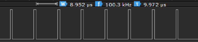
This generated a 100KHz signal. You will notice the discrepancy of the duty cycle; the high time is 1us but the low time is 9us. That's because it took 8us to execute the while(n--) portion of the loop.
Now let us replace it with a Duff's device:
#define PULSE() output_toggle(PIN_PULSE); \
output_toggle(PIN_PULSE)
void send(int n)
{
switch(n)
{
case 8:
PULSE();
case 7:
PULSE();
case 6:
PULSE();
case 5:
PULSE();
case 4:
PULSE();
case 3:
PULSE();
case 2:
PULSE();
case 1:
PULSE(); } }
In the above example, the switch(n) creates a jump table of up to 8 pulses and jumps to position with n pulses. After the jump is calculated and executed, the following pulses run without any other conditional code. Lets look at the timing of pulses generated on a PIC18F running at 4MHz (one instruction every 1us):
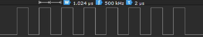
This creates a 500KHz signal, 5 times faster than using a while loop. Also of interest is the duty cycle of the signal, which is now 50% (even time high and low) because the pulses execute without any other conditional checks. If you look at the LST file to view the instructions generated, the reason for this is clear (BTG instruction is used to perform a bit toggle, in this case toggling the register that controls this GPIO pin):
.................... case 8:
.................... PULSE();
00016: BTG 3FBD.0
00018: BTG 3FBD.0
.................... case 7:
.................... PULSE();
0001A: BTG 3FBD.0
0001C: BTG 3FBD.0
.................... case 6:
.................... PULSE();
0001E: BTG 3FBD.0
00020: BTG 3FBD.0
The next time you have a loop and you were looking to optimize it for speed, the Duff's device is a great method for accomplishing this!
Like us on Facebook. Follow us on Twitter.
About CCS:
CCS is a leading worldwide supplier of embedded software development tools that enable companies to develop premium products based on Microchip PIC ® MCU and dsPIC ® DSC devices. Complete proven tool chains from CCS include a code optimizing C compiler, application specific hardware platforms and software development kits. CCS' products accelerate development of energy saving industrial automation, wireless and wired communication, automotive, medical device and consumer product applications. Established in 1992, CCS is a Microchip Premier 3rd Party Partner. For more information, please visit http://www.ccsinfo.com.
PIC ® MCU, MPLAB ® IDE, MPLAB ® ICD2, MPLAB ® ICD3 and dsPIC ® are registered trademarks of Microchip Technology Inc. in the U.S. and other countries. | July 22, 2020 Expand to read article below The CCS C Compiler has added built-in Local Interconnect Network (LIN) bus support to the #use rs232() library. LIN bus is an inexpensive serial communication protocol used primarily in the automotive industry to complement the existing CAN Bus network. The LIN bus network contains one master node and up to 15 slave nodes for a total of 16 nodes, and supports bit rates up to 20 kbit/s.
The LIN bus protocol's message frame consist of two parts, the header and the response. The header is always sent by the master node, meaning all communication is initiated by the master node. After the header is sent only one node sends the response. The header consists of three main fields, the break field, the sync field and the identifier field. The break field is used to get the attention of all LIN slave nodes on the network. The sync field is the hexadecimal value 0x55 used by the slave nodes to determine the current bit time of the bus. Finally the identifier field is used to determine which node will respond during the response part of the frame. The response consist of two fields, the data field and the checksum field. The data field contains 0 to 8 bytes and the checksum field is one byte. Depending on the LIN bus protocol specification being used the checksum is either the checksum of the data field bytes, or the identifier field and the data field bytes.
The following options have been added to the CCS C Compiler's #use rs232() library to enable LIN bus master or slave protocol support, LIN=MASTER and LIN=SLAVE. Additionally the options LIN_CHECKSUM=LEGACY or LIN_CHECKSUM=ENHANCED can be used to select which checksum type is used by default by the functions. Legacy checksum only uses the data field when calculating the checksum, and enhanced uses both the identifier field and the data field when calculating the checksum.
Whether a device can use the library's built-in LIN bus protocol support depends on the mode being used and configuration. When setup as a LIN bus master both software and hardware configurations are support, the only limitation is that when using the hardware UART peripheral the device is required to have an advanced UART peripheral or an UART peripheral with built-in protocol support. When setup as a LIN bus slave it's only supported when using the hardware UART peripheral on devices that have an advanced UART peripheral or an UART peripheral with built-in protocol support. For devices that have a hardware UART peripheral, most devices have a UART peripheral that will work with the #use rs232() library's built-in LIN bus protocol.
When built for a LIN bus master the following functions are added by the #use rs232() library: linbus_header(), linbus_rx_response(), linbus_tx_response() and linbus_checksum_type(). The linbus_header() function is used to by the master to send the header part of the LIN bus message frame, the parity bits of the identifier field is automatically calculated by the function. The linbus_rx_response() function is used by the master to receive the response from one of the slave nodes during the response part of the LIN bus message frame. The linbus_tx_response() function is used by the master to transmit the response during the response part of the LIN bus message frame, the master node only sends the response when the identifier it sent indicates that it should transmit the response. Finally the linbus_checksum_type() function can be used to change how the linbus_tx_response() function calculates the checksum that it sends when used to send the response part of the LIN bus message frame.
When built for a LIN bus slave the following functions are added by the #use rs232() library: linbus_header_hit(), linbus_header_get(), linbus_rx_response(), linbus_tx_response() and linbus_checksum_type(). The linbus_header_hit() function is used to determine if the header as been received. For devices that have a UART with build-in protocol support this function returns TRUE after the entire header as been received, and for devices with an advanced UART it returns TRUE after the first 8 bits of the break byte is received. The linbus_rx_header() function is used to retrieve the identifier field of the received header, the parity bits masked off. Additionally for devices with an advanced UART peripheral this functions also sets up the UART peripheral to receive the sync field. The linbus_rx_response() function is used by the slave to receive the response from another node during the response part of the LIN bus message frame. For devices with a UART peripheral with built-in protocol support this function only needs to be called if the received identifier indicates that the message is to be received by that node. For devices with an advanced UART this function should be called for all messages were the received identifier doesn't indicates that the node should transmit the response. The linbus_tx_reponse() function is used by the slave to transmit the response during the response part of the LIN bus message frame. This function should only be called when the received identifier indicates that the node should transmit the response. Finally the linbus_checksum_type() function can be used to change how the linbus_tx_response() function calculates the checksum that it sends when used to send the response part of the LIN bus message frame.
Like us on Facebook. Follow us on Twitter.
About CCS:
CCS is a leading worldwide supplier of embedded software development tools that enable companies to develop premium products based on Microchip PIC® MCU and dsPIC® DSC devices. Complete proven tool chains from CCS include a code optimizing C compiler, application specific hardware platforms and software development kits. CCS' products accelerate development of energy saving industrial automation, wireless and wired communication, automotive, medical device and consumer product applications. Established in 1992, CCS is a Microchip Premier 3rd Party Partner. For more information, please visit http://www.ccsinfo.com.
PIC® MCU, MPLAB® IDE, MPLAB® ICD2, MPLAB® ICD3 and dsPIC® are registered trademarks of Microchip Technology Inc. in the U.S. and other countries. | September 1, 2020 Expand to read article below The CCS C Compiler provides an extremely flexibly serial library; it has the ability to use the hardware peripheral or bit bang the pins, to control and monitor flow control, to specify parity, to use a one wire bus, and more. One feature it has is the ability to specify a receive buffer, and the library will automatically use the receive interrupt to buffer incoming characters. Here is an example of creating a stream called STREAM_UART1 on the UART1 hardware peripheral with a 16 byte receive buffer:
#use rs232(UART1, baud=9600, receive_buffer=16, stream=STREAM_UART1)
Essentially the stream works like a file handle that can be used with C standard I/O functions like fputc, fgetc, etc. Using the stream created above, here is a simple loop that echoes data received on the UART back to the UART:
while (kbhit(STREAM_UART1))
{
fputc(fgetc(STREAM_UART1), STREAM_UART1); }
This example shows the flexibility of the #use rs232() library provided by CCS. The 'receive_buffer' option creates an interrupt on the UART receive to buffer incoming characters and kbhit() and fgetc() accesses that buffer, but if the 'receive_buffer' was removed from the #use rs232(), then kbhit() and fgetc() would instead check for any received data being held by the UART.
The 'receive_buffer' example as shown above has no way of notifying the users software that data is available, except by polling the receive buffer status with kbhit(). The 5.095 version of the CCS C Compiler adds a new option called 'callback' that allows the user to specify a function to be called when the receive buffer goes from empty to not empty. This could be used to mark a semaphore or enable a routine to start parsing data in the receive buffer. Here is an example of adding this new option:
#use rs232(UART1, baud=9600, receive_buffer=16, stream=STREAM_UART1, \
callback=Uart1On
As stated earlier, this example will call the 'Uart1OnRx' function whenever the receive buffer goes from empty to not empty. Here is how the earlier echo example can be changed to use an RTOS with a semaphore to mark when the receive buffer is ready:
#use rtos(timer=0)
int uart_sem = 0;
static void Uart1OnRx(void) {
rtos_signal(uart_sem); }
#task(rate=10ms)
static void Uart1Task(void) {
for(;;) {
rtos_wait(uart_sem);
while(kbhit(STREAM_UART1)) {
fputc(fgetc(STREAM_UART1), STREAM_UART1); } } }
Alternatively, a function for parsing data in the receive buffer can be queued for execution with the timeouts library:
#include <timeouts.c>
void Uart1OnxTimeout(void* pArgs) {
while(kbhit(STREAM_UART1)) {
putc(getc(STREAM_UART1), STREAM_UART1); } }
static void Uart1OnRx(void) {
TimeoutsAdd(Uart1OnxTimeout, NULL, 0); }
Like us on Facebook. Follow us on Twitter.
About CCS:
CCS is a leading worldwide supplier of embedded software development tools that enable companies to develop premium products based on Microchip PIC ® MCU and dsPIC ® DSC devices. Complete proven tool chains from CCS include a code optimizing C compiler, application specific hardware platforms and software development kits. CCS' products accelerate development of energy saving industrial automation, wireless and wired communication, automotive, medical device and consumer product applications. Established in 1992, CCS is a Microchip Premier 3rd Party Partner. For more information, please visit https://www.ccsinfo.com.
PIC ® MCU, MPLAB ® IDE, MPLAB ® ICD2, MPLAB ® ICD3 and dsPIC ® are registered trademarks of Microchip Technology Inc. in the U.S. and other countries. |
|


