April 22, 2021  Expand to read article below Expand to read article belowIntroducing the new CCS Long Range RF Development Kit. LoRa® is low-power wide-area network protocol that can be used to periodically communicate sensor data. LoRa® uses a proprietary spread spectrum modulation that is similar to and a derivative of Chirp Spread Spectrum (CSS) modulation. This allows for long-range transmission, up to 9 miles, with low power consumption. This makes it ideal for battery applications that only needs to periodically transmit sensor data.
The CCS Long Range RF Development Kit comes with two development boards with Microchip's RN2903 modules. The RN2903 modules are designed to communicate using LoRa® modulation using the US frequency band. This is everything needed to develop a LoRa® peer-to-peer (P2P) implementation. The development kit's exercise manual has several exercises for setting up testing different types of LoRa® P2P networks using the provided RN2903 and LoRa® P2P drivers.
Additionally, the development kit can be used the to develop code to communicate on a LoRaWAN®network. LoRaWAN® is a upper level network protocol, developed by the LoRa® Alliance, that uses LoRa® modulation for creating a cloud-based network. In LoRaWAN® networks end-devices periodically send messages to a gateway, which forwards it to a network server which in turn forwards the message to an application server. Any response for the end-device is then forward back in the reverse order. The development kit can be used to develop and test end-devices for a LoRaWAN® implementation, using the provided RN2903 and LoRaWAN® driver. Testing the LoRaWAN® end-device will require at minimum an external LoRaWAN® gateway, not provided with the Long Range RF Development Kit.
LoRaWAN® is a mark used under license from the LoRa Alliance®. Use of the LoRa Alliance® and LoRa Alliance® Member marks is pursuant to license from the LoRa Alliance®.
Like us on Facebook. Follow us on Twitter.
About CCS:
CCS is a leading worldwide supplier of embedded software development tools that enable companies to develop premium products based on Microchip PIC® MCU and dsPIC® DSC devices. Complete proven tool chains from CCS include a code optimizing C compiler, application specific hardware platforms and software development kits. CCS' products accelerate development of energy saving industrial automation, wireless and wired communication, automotive, medical device and consumer product applications. Established in 1992, CCS is a Microchip Premier 3rd Party Partner. For more information, please visit https://www.ccsinfo.com.
PIC® MCU, MPLAB® IDE, MPLAB® ICD2, MPLAB® ICD3 and dsPIC® are registered trademarks of Microchip Technology Inc. in the U.S. and other countries. | April 22, 2021 Expand to read article below The CCS C Compiler supports C++ like function overloading. Function overloading allows the user to develop two functions with the same name, but have different parameters or return types. The CCS C Compiler can distinguish between RAM and ROM pointers when overloading. This is useful on the PIC® MCU which uses the Harvard architecture, meaning accessing the RAM and ROM is different. Since accessing RAM and ROM is different, the compiler needs to know which one the user is accessing so it can use the proper method.
Here is a simple example of function overloading using ROM and RAM pointers:
int Checksum(rom char * ptr) {
int cs;
while(*ptr!=0) // *ptr reads from ROM
cs += *ptr;
return cs; }
int Checksum(char * ptr) {
int cs;
while(*ptr!=0) // *ptr reads from RAM
cs += *ptr;
return cs; }
...
char data[10] = "Foo Bar";
const char hex[] = "0123456789ABCDEF";
label_cs = checksum("Hello World"); // Calls first funct
hex_cs = checksum(hex); // Calls first funct
data_cs = checksum(data); // Calls second funct
Checksum() has two functions, one for handling ROM pointers and one for handling RAM pointers. In the CCS C Compiler the 'rom' keyword specifies the ROM flash memory, if this is not specified the CCS C Compiler will use RAM. When Checksum() is called with the "Hello World" as a 'rom char *'
Some compiler built in functions deal with conversions from ROM to RAM pointers. For example strcpy() has two forms:
strcpy(ramstring, "Hello World");
strcpy(ramstring, buffer);
This is so the compiler can easily deal with awkward syntactical issues like this:
char string[] = "ABCDEFGHIJ";
ROM string moved to RAM and string is a RAM pointer. The CCS C Compiler also supports this syntax with all the appropriate conversions:
char string[10];
string = "Hello World";
Note that %s in a printf() is able to figure out if the string is in RAM or ROM however most string functions in string.h do not have overloaded versions for ROM data. For example if you want to do strcat(string,"...") then you must first make a function like this:
char *strcat(char *s1, rom char *s2)
{
unsigned char *s;
for (s = s1; *s != '\0'; ++s);
while(*s2 != '\0')
{
*s = *s2;
++s;
++s2; }
*s = '\0';
return(s1); }
Here is a more complex example of function overloading based on ROM and RAM pointers:
struct {
union {
rom char* pRom;
char* pRam; };
int1 isRom; } savedString;
void SetSavedString(rom char* pRom) {
savedString.pRom = pRom;
savedString.isRom = TRUE; }
void SetSavedString(char* pRam) {
savedString.pRam = pRam;
savedString.isRom = FALSE; }
void PrintSavedString(void) {
if(savedString.isRom)
printf("%s", savedString.pRom); else
printf("%s", savedString.pRam); }
SetSavedString((rom char*)"Hello World");
SetSavedString((char*) "foo bar");
SetSavedString() saves a (char*) or (rom char*) depending on what was passed in by the user to memory, and sets a flag denoting the type of pointer that is being used. The PrintSavedString() checks the flag to select the proper pointer, and prints the string.
Like us on Facebook. Follow us on Twitter.
About CCS:
CCS is a leading worldwide supplier of embedded software development tools that enable companies to develop premium products based on Microchip PIC ® MCU and dsPIC ® DSC devices. Complete proven tool chains from CCS include a code optimizing C compiler, application specific hardware platforms and software development kits. CCS' products accelerate development of energy saving industrial automation, wireless and wired communication, automotive, medical device and consumer product applications. Established in 1992, CCS is a Microchip Premier 3rd Party Partner. For more information, please visit https://www.ccsinfo.com.
PIC ® MCU, MPLAB ® IDE, MPLAB ® ICD2, MPLAB ® ICD3 and dsPIC ® are registered trademarks of Microchip Technology Inc. in the U.S. and other countries. | March 18, 2021 Expand to read article below In part one we covered the two hardware address spaces in the PIC® MCU and how they can be used from C. Part two explained how a developer defines virtual address spaces. In this article we will detail how some PIC® MCUs have their own alternative address spaces and how the C compiler deals with them.
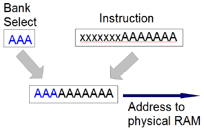
First, we must have a basic understanding about the fundamental addressing at the hardware level. Consider a PIC16F887 part and the instruction to add a memory value to the working register and put the result in the working register. The 14 bit instruction looks like this:
0 0 0 1 1 1 0 a a a a a a a
The aaaaaaa is the address in memory to get the data from. Notice there are only 7 bits so the address range is 0-127. In order to gain access to the rest of memory, there are some bank select bits. If the bank select bits are set to 010 then the instruction with aaaaaaa set to 0000001 will actually access memory location 0100000001. Fortunately, the compiler (at least the CCS C compiler) takes care of setting the right bank select bits before any instruction that needs the bits changed. There is a similar method used for program memory where the bits are called the page select bits. That comes into play with goto's and calls.
The following topics cover special features in some PIC ® MCU parts that allow for a more effective way to access memory.
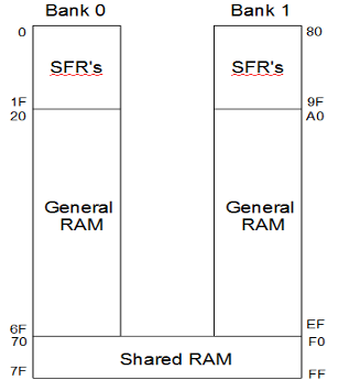
Mid-range Shared RAM
Even the old PIC chips had some special function registers duplicated in every bank, so there is no need to switch banks to access a popular register, like the status register. Many of the newer PIC ® MCUs also have some general purpose RAM duplicated in all the banks. For example, on the PIC16F887 locations 0x70-0x7F reference the same RAM locations regardless of the bank bit setting. That means 0x70 and 0x1F0 are the same location. It is for this reason the compiler scratch locations begin at 0x70.
 Mid-range Linear Address Space
On the mid-range parts the special function registers typically are at the start of each bank. For example 0x00 to 0x1F are SFR and 0x20-0x7F is general RAM. Then 0x80 to 0x1F are SFR and 0xA0 to 0xFF has general RAM. This means the largest data structure a user can have in RAM is 96 bytes or 80 bytes if there is shared RAM. If the user needs a larger array for example, they would need to split it into two smaller arrays.
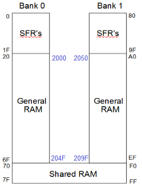
On some mid-range PIC ® MCUs there is an extended instruction set (4 and 5 digit parts after the F). In these parts there is a second way to access RAM called linear addressing. The linear address space has all the general purpose RAM locations and none of the SFR's. The entire general purpose RAM is put at location 0x2000 and up. Location 0x2000 is the same as 0x20. Location 0x02050 is the same as 0xA0. Now users can have data structures as large as memory can hold. The only way to address using the linear method is using indirection via the FSR registers. In the CCS C Compiler anytime a user accesses a data item using a variable index the linear addressing method is used if available on the part.
PIC18 Access Space
On the PIC18 parts most instructions have what is called an access bit to select what address space is used in the instruction. In the normal mode, the addressing works like the PIC16 using bank select bits somewhere else to fully specify the address. However, if the access bit is 0 then the address in the instruction is used to access only certain registers. The add instruction on the PIC18F4520 looks like this:
0 0 1 0 0 1 0 x a a a a a a a a
When x (the access bit) is 1 the address in the instruction is combined with the bank select bits to form the physical address.
When x is 0 then the physical address depends on the value of the address. With lower addresses then the remaining address bits are used as-is to get the physical address without using the bank select bits. For example, 00000001 will give users physical address 1 regardless of the bank select bit setting. This is kind of like the shared RAM feature in the PIC16. When the address is higher (0x80 and up on the PIC18F4520) then 0xF80 is added to the address over the cutoff to get the physical address. This allows for access to special function registers regardless of the bank select bit setting. Be aware however that different PIC18 parts have a different split between general purpose RAM and the SFR's in the access space. The PIC18F4520 has 128 bytes in each however the PIC18F4550 has only 96 bytes in general RAM and the rest in SFR's.
It should also be pointed out the PIC18 has a special double word instruction that can copy from any RAM address to any other RAM address.
PIC18 XINST
Most PIC18 parts have a XINST bit in the configuration fuses. When this bit is set the way the general purpose RAM is accessed when the access bit is set is modified. Instead of accessing the RAM directly the address is first added to the contents of another register. The intent with this feature is to make the using local variables easier in C code where users could have variables on a stack. This would allow for recursive functions. Since this feature is either on or off for the whole CCS has decided not to add support in the compiler for XINST because of the rare need for recursion and the inefficiencies caused by using this mode.
PIC24/DSPIC Extended RAM
On the 24 bit parts, the bank select bits were removed. Looking at the same add instruction it looks like this:
1 0 1 1 0 1 0 0 0 0 0 a a a a a a a a a a a a a
That means the instruction has direct access to RAM locations 0-1FFF (8K). That is a lot but many of these parts have more RAM than that. There are two ways to access RAM above 1FFF. First is to indirectly access the RAM using a 16 bit pointer (64K). This does require an extra instruction or two but is not as bad as it sounds since many instructions allow indirect addressing using one of the working registers. The other method is to use a special instruction to copy to/from any address 0-FFFF (64K) and a working register.
In summary, we have a great way to access 8K of RAM and there is a method to get at RAM over 8K but the method needs to be repeated for each access.
PIC24/DSPIC PSV Mode
Access to program memory (for constants) requires some extra steps to set up some registers and grab the data. The 24 bit parts have a mode that can be used to map the upper 32K of RAM addresses on to a selected area of program memory. This can be used to access constants in program memory as easily as if they were in RAM. When doing this, users loose access to the upper 32K of RAM. By default the CCS Compiler does not use this technique because in general it seems additional RAM is more important than fast access to ROM. A lot of the Microchip example code does use PSV mode so there is support in the CCS compiler to allow for easier porting.
#device PSV=16 // Turns on PSV mode
const char serial_number[] = {"123456789"}; // Saved in ROM
...
sn = atol32(serial_number); // Is accessed by a RAM address
Like us on Facebook. Follow us on Twitter.
About CCS:
CCS is a leading worldwide supplier of embedded software development tools that enable companies to develop premium products based on Microchip PIC ® MCU and dsPIC ® DSC devices. Complete proven tool chains from CCS include a code optimizing C compiler, application specific hardware platforms and software development kits. CCS' products accelerate development of energy saving industrial automation, wireless and wired communication, automotive, medical device and consumer product applications. Established in 1992, CCS is a Microchip Premier 3rd Party Partner. For more information, please visit https://www.ccsinfo.com.
PIC ® MCU, MPLAB ® IDE, MPLAB ® ICD2, MPLAB ® ICD3 and dsPIC ® are registered trademarks of Microchip Technology Inc. in the U.S. and other countries. | March 18, 2021 Expand to read article below There are situations where there is a need to make repetitive but identical changes to each line, or copy a block of text and then add the same text or spacing to each line when editing source code. Column editing allows a way to enter or delete text on multiple rows at once.
Access this feature by pressing the CTRL key while making a selection with the left mouse button. This enables selecting a rectangular region to be able to type to replace its contents, paste over it, or delete it.
The following are some examples.
1. Editing identical variable types
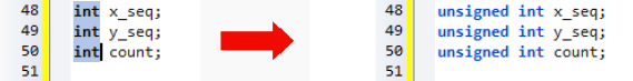
In the above illustration, column select the "int" type, and then simply type "unsigned int", to all 3 lines at once.
2. Working with Enums
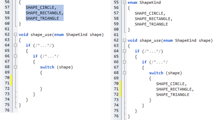
Above shows a selected rectangle consisting of all of the enum variants to avoid copying the spacing. Pasting it into the switch statement maintains its tabbing. Next insert "case" into each line by simply column select the space before "SHAPE" and type "case".
Like us on Facebook. Follow us on Twitter.
About CCS:
CCS is a leading worldwide supplier of embedded software development tools that enable companies to develop premium products based on Microchip PIC® MCU and dsPIC® DSC devices. Complete proven tool chains from CCS include a code optimizing C compiler, application specific hardware platforms and software development kits. CCS' products accelerate development of energy saving industrial automation, wireless and wired communication, automotive, medical device and consumer product applications. Established in 1992, CCS is a Microchip Premier 3rd Party Partner. For more information, please visit https://www.ccsinfo.com.
PIC® MCU, MPLAB® IDE, MPLAB® ICD2, MPLAB® ICD3 and dsPIC® are registered trademarks of Microchip Technology Inc. in the U.S. and other countries. | March 18, 2021 Expand to read article below Often times the "Out of ROM, a segment or the program is too large" error pops up near the end of a project and users are now forced to deal with this new problem. This article will help to understand the causes and some simple solutions to get back to the project.
About Segment Sizes
The first thing to realize is that users may get this error and have plenty of ROM left. The reason is the CCS C Compiler does not split a function across a ROM page boundary. This error message always produces some informational lines in the .err file to help understand what is going on. Here is an example output for the case where a function is too large for a segment.
C:PICmain.c:1231:1: Error#71 Out of ROM, A segment or the program is too large
process_data
Seg 00000-00002, 0000 left, need 009C7 Reserved
Seg 00003-00003, 0001 left, need 009C7
Seg 00004-00055, 0000 left, need 009C7 Reserved
Seg 00056-007FF, 003D left, need 009C7
Seg 00800-00FFF, 042E left, need 009C7
Seg 01000-017FF, 0800 left, need 009C7
Seg 01800-01FFF, 0800 left, need 009C7
Seg 02000-027FF, 0800 left, need 009C7
Seg 02800-02FFF, 0800 left, need 009C7
Seg 03000-037FF, 0800 left, need 009C7
Seg 03800-03FFF, 0800 left, need 009C7
The first thing to notice is the "process_data." This is the name of a function in the users program that caused the linker to stop. Then look at the number after "need", this is how many words would be needed for that function (process_data). Sometimes it is different in different areas of memory because extra instructions are needed to jump to other pages.
The ROM in the chip is split into segments. Each segment is shown in this list. The first and third are marked as reserved, this is the reset jump and interrupt handler. These segments cannot be relocated. Of the remaining segments you will notice there is never more than 800 (2K) available (left). This is because on this chip the page size is 0x800.
There is plenty of ROM available on this chip but the function takes 9C7 and that does not fit into the 800 segment size. The simple solution is to split the function into two.
We most commonly see this error in technical support with main() as the function and there are no other functions in the program. It is always good to adapt a coding style where there are some limits on function size to aid in readability, maintainability and to keep sanity. It is recommended that a function should fit on a screen or at least a page.
It is possible to get an error like the above when users have a well structured program with lots of small functions. Consider the following example:
void func_b(void) {
...
}
void func_c(void) {
...
}
void func_d(void) {
...
}
void func_a(void) {
funct_b();
funct_c();
funct_d(); }
If funct_b(), funct_c() and funct_d() are each only called once then the compiler to save valuable stack space will copy the code from those functions to funct_a(). This makes funct_a() way bigger that it appears.
To solve the problem users can tell the compiler to never inline the function like this:
#separate
void func_b(void) {
...
}
Note that when prototyping the function there must also have the #separate there.
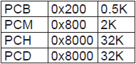
Here are the page (max segment) sizes for each family:
 Fragmentation
Another problem maybe the way the segments are being used. Users can see something like this:
Seg 00000-00002, 0000 left, need 00261 Reserved
Seg 00003-00003, 0001 left, need 00261
Seg 00004-00055, 0000 left, need 00261 Reserved
Seg 00056-007FF, 003D left, need 00261
Seg 00800-00FFF, 022E left, need 00261
Seg 01000-017FF, 00F7 left, need 00261
Seg 01800-01FFF, 0005 left, need 00261
Seg 02000-027FF, 0193 left, need 00261
Seg 02800-02FFF, 0073 left, need 00261
Seg 03000-037FF, 011B left, need 00261
Seg 03800-03FFF, 0175 left, need 00261
In total you have enough RAM for your function of size 261 but not all in the same segment. The linker does try to shift functions around and make room, but if this is not possible you will get the error. The best way to solve this is to again split some larger functions into smaller functions. If there are more smaller functions the linker will be able to shuffle things around and make more room in one of the segments for your 261 function.
To find out how much ROM each functions used in the IDE use COMPILE > STATISTICS. There needs to be an error free compile to see this however.
Code Optimization
If users are really out of ROM then they need to consider optimizing your code. The general rule is to find groups of lines that are the same or similar and move them to a function. The compiler does some optimization between statements, but most of the optimization is done on a single statement. Skimming through the .LST file to identify C lines that generate a lot of assembly can help to identify areas that users may want to check for the possibility to move to a function. Here are some examples:
1. Even though this appears to be a simple initialization you will save ROM by moving the four lines to a function:
next_in=0;
next_out=0;
count=0;
total=0.0;
read_from_history();
...
next_in=0;
next_out=0;
count=0;
total=0.0;
read_from_device();
2. Unless using #opt compress (see below) the compiler does not optimize the subscript expression used here:
weight = weight_lookup[width*height+cal_offset];
time = time_lookup[width*height+cal_offset];
When possible do this:
volume = width*height+cal_offset;
weight = weight_lookup[volume];
time = time_lookup[volume];
3. When reviewing the LST file users will see printf's can take a lot of space. For code like this:
printf("Max position = %lu:%lurn", max_x, max_y);
printf("Ave position = %lu:%lurn", ave_x, ave_y);
printf("Min position = %lu:%lurn", min_x, min_y);
Consider:
void printxy( rom char * label, int16 x, int16 y) {
printf("%s position = %lu:%lurn", label, x, y); }
...
printxy("Max", max_x, max_y);
printxy("Ave", ave_x, ave_y);
printxy("Min", min_x, min_y);
Compiler Optimization
By default the compiler uses optimization level 9. This provides a good level of optimization that has been well tested. If the optimization is set down then now is a good time to get it back up to 9. If there are any optimization problems do report then to support so we can fix them.
Some chips have a more extreme level of optimization available. To invoke it use:
#opt compress
This optimization will save ROM but will take longer to run. What the compiler does is to go through the whole program and any sequence of instructions that is repeated are made into a function that is called each time it is needed. This will make debugging and even reading the .LST file more difficult. The savings can be substantial and may prevent users from moving to a larger chip.
Like us on Facebook. Follow us on Twitter.
About CCS:
CCS is a leading worldwide supplier of embedded software development tools that enable companies to develop premium products based on Microchip PIC ® MCU and dsPIC ® DSC devices. Complete proven tool chains from CCS include a code optimizing C compiler, application specific hardware platforms and software development kits. CCS' products accelerate development of energy saving industrial automation, wireless and wired communication, automotive, medical device and consumer product applications. Established in 1992, CCS is a Microchip Premier 3rd Party Partner. For more information, please visit https://www.ccsinfo.com.
PIC ® MCU, MPLAB ® IDE, MPLAB ® ICD2, MPLAB ® ICD3 and dsPIC ® are registered trademarks of Microchip Technology Inc. in the U.S. and other countries. | February 19, 2021 Expand to read article below The CCS C compilers are a great tool for programming Microchip PIC® microcontrollers however, there is not a version of the compiler available for use on macOS. Despite this, there is a way for Mac users to utilize the CCS C compilers by using a virtual machine. A virtual machine is like a fully functioning computer but it is running in software on a host computer. By using a virtual machine, a macOS user can run a Windows 10 computer from their Mac. This allows the CCS C compilers to be run on a macOS computer.
There is an article on the CCS website that includes a step-by-step guide to using CCS C compilers on macOS (a link to this guide is at the end of this article). The article walks through installing and editing a driver created by FTDI which allows a Mac machine to communicate with the ICD that is used when programming/debugging MCUs. In the guide, it is recommended to use a free app called Xcode that is available on the app store, which makes editing the driver easier and more user friendly.
After the driver from FTDI is installed, the guide outlines how to create a virtual machine on a Mac computer. It starts with installing VirtualBox, a virtualization tool that allows for the creation and management of a virtual machine. The guide walks through how to create a virtual machine through VirtualBox, as well as how to download an ISO image of Windows 10 so the operating system can be installed on the virtual machine.
Once a virtual machine has been created and an ISO image has been attached to it, the machine can be booted and the Windows 10 installation process begins. The guide provides steps to format the virtual hard drive that is used by the virtual machine so that the files for Windows 10 can be copied over correctly and installed. After the OS is installed, the user can follow the Windows 10 setup and enter their own preferences.
The final step outlined in the guide is setting up the Windows 10 environment so that it can run the CCS software. This includes installing USB drivers from CCS so that the virtual machine can detect the ICD when it is passed through from macOS. The guide also outlines creating a shared folder between the host macOS machine and the Windows 10 virtual machine. Creating a shared folder allows for the CCS C compiler installation files to be transferred to the VM so the software can be installed. Once you have completed the step-by-step guide to using CCS C compilers on macOS, you will be able to program Microchip PIC® MCUs without the use of a Windows computer.
For more information, view the full article here:
https://www.ccsinfo.com/faq.php?page=compiler_mac
Like us on Facebook. Follow us on Twitter.
About CCS:
CCS is a leading worldwide supplier of embedded software development tools that enable companies to develop premium products based on Microchip PIC® MCU and dsPIC® DSC devices. Complete proven tool chains from CCS include a code optimizing C compiler, application specific hardware platforms and software development kits. CCS' products accelerate development of energy saving industrial automation, wireless and wired communication, automotive, medical device and consumer product applications. Established in 1992, CCS is a Microchip Premier 3rd Party Partner. For more information, please visit https://www.ccsinfo.com.
PIC® MCU, MPLAB® IDE, MPLAB® ICD2, MPLAB® ICD3 and dsPIC® are registered trademarks of Microchip Technology Inc. in the U.S. and other countries. | February 19, 2021 Expand to read article below In part one, we covered the two hardware address spaces in the PIC® MCU and how they can be used from C. This article will explain how a developer defines virtual address spaces. These user defined spaces can be used to add a layer of abstraction between "normal" C variables and the actual hardware memory implementation. We will detail implementations for three example address spaces:
* External serial EEPROM
* Display memory in a graphic LCD module
* Dual copy safety variables for a safety critical application
External Serial EEPROM
For the first example, we will use an external serial EEPROM that uses I2C to access the data. CCS provides a simple driver that gives users write_ext_eeprom() and read_ext_eeprom() for byte access to the external memory. To use that memory like they would use regular RAM users need to create a new address space that the variable can be declared in.
Before users can define the address space, users need to provide some functions to read and write to the memory. For example:
void DataEE_Read(int32 addr, int8 * ram, int bytes) {
for(int i=0;i<bytes;i++,ram++,addr++)
*ram=read_ext_eeprom(addr); }
void DataEE_Write(int32 addr, int8 * ram, int bytes) {
for(int i=0;i<bytes;i++,ram++,addr++)
write_ext_eeprom(addr,*ram); }
When the embedded C ANSI specification was first proposed they called this typemod and by the time the specification was approved it was called addressmod with a new syntax. The CCS C compiler accepts both syntax forms. This is everything needed to define the space:
addressmod (DataEE, DataEE_read,DataEE_write,0,0x3ff);
The first parameter give the new space a name, then we have the read and write functions and finally we have the address range of the new space. Here is how it can be used:
DataEE int32 serial_number;
serial_number=0x123456789;
printf("S/N = %8LXrn", serial_number);
In this case, the variable serial number actually resides in the external EEPROM. Suppose the user wants to make the EEPROM access more efficient.They could crate a simple RAM array with a copy of all the EE data that gets loaded on power up.Then the DataEE_Read() function reads from the RAM array and DataEE_Write() writes to the array while marking a dirty bit. In the background as time permits some task could copy the dirty data back to the EE.The details of this implementation are separate from the main program and the algorithm can be changed without affecting the main program.For example, maybe the user want to keep a CRC of the EE data in the last EE location, or they want to encrypt the data or keep three copies of each byte in the EE in case of corruption.This can be completely handled in DataEE_Write(). Data can be declared with the DataEE qualifier with arrays, structures or any other data type.
Display Memory in a Graphic LCD Module
Consider an array where each element in the array represents a color of a pixel on a display. If the processor shares memory with the display then this is a given. However, for displays with a serial interface or requires commands to access the display users can use a user defined space to have the same capability. The functions might look like this:
void LCD_Read(int32 addr, int8 * ram, int bytes) {
glcd_ReadPixels(addr*LCD_WIDTH*sizeof(color_t), // X
addr % (LCD_WIDTH*sizeof(color_t)), // Y
bytes/sizeof(color_t),1,ram); }
void LCD_Write(int32 addr, int8 * ram, int bytes) {
glcd_DrawPixels(addr*LCD_WIDTH*sizeof(color_t), // X
addr % (LCD_WIDTH*sizeof(color_t)), // Y
bytes/sizeof(color_t),1,ram); }
addressmod (LCD_screen, LCD_read,LCD_write,0,0x3ff);
LCD_screen char screen[180][240];
A function to draw a line might look like this:
void draw_line( int16 x, int16 y, int16 length, color_t color){
for(int16 i=x; i<(x+length); i++)
screen[y][i]=color; }
Dual Copy Safety Variables for a Safety Critical Application
Consider an application where to get certified users are required to save all critical variables in two memory locations and to verify they match before using them. Users can add logic to the hundreds of places they access the variables. It would be easier with macros however it will still make the code hard to read and if the variables considered critical changes then it can be a mess to update the code. Instead try this:
void Safety_Read(int32 addr, int8 * ram, int bytes) {
for(int i=0;i<bytes;i++,ram++,addr++)
if(safety_ram1[addr]!=safety_ram2[addr])
trigger_system_fault('Bad RAM'); else
*(ram)=safety_ram1[addr]; }
void Safety_Write(int32 addr, int8 * ram, int bytes) {
for(int i=0;i<bytes;i++,ram++,addr++) {
safety_ram1[addr]=*(ram);
safety_ram2[addr]=*(ram); } }
Then the critical variables can be declared like this:
SafetyRAM int16 motor_speed;
SafetyRAM int16 recent_presures[10];
SafetyRAM struct {
int32 target_voltage; // tenths of a volt
int16 time_since_change; // seconds
int8 last_adjustment; // tenths of a volt } drive_data;
In the above discussion, we covered how to implement user defined address spaces. The next part details how some PIC ® MCUs have their own alternative address spaces and how the C compiler deals with them. For example the enhanced PIC16 parts have both a physical address space in the traditional memory banks and they have an alternate linear address space that includes only the user RAM locations and no Special Function Registers. Some PIC18's and PIC24's also have alternate addressing schemes.
Like us on Facebook. Follow us on Twitter.
About CCS:
CCS is a leading worldwide supplier of embedded software development tools that enable companies to develop premium products based on Microchip PIC ® MCU and dsPIC ® DSC devices. Complete proven tool chains from CCS include a code optimizing C compiler, application specific hardware platforms and software development kits. CCS' products accelerate development of energy saving industrial automation, wireless and wired communication, automotive, medical device and consumer product applications. Established in 1992, CCS is a Microchip Premier 3rd Party Partner. For more information, please visit https://www.ccsinfo.com.
PIC ® MCU, MPLAB ® IDE, MPLAB ® ICD2, MPLAB ® ICD3 and dsPIC ® are registered trademarks of Microchip Technology Inc. in the U.S. and other countries. | February 19, 2021 Expand to read article below The CAN protocol is a serial communication protocol that is used in the automotive industry for communicating between devices inside of a vehicle, the engine control unit and dashboard for example. Data is sent in frames and is done in such a way that if more then one device transmits at the same time the highest priority device is able to continue while the other device back off. There are two CAN standards that are in use today, CAN 2.0 and CAN FD. CAN 2.0 is the older of the two protocols and has two parts; part A is for the standard format with an 11-bit identifier, commonly called CAN 2.0A, and part B if for the extended format with a 29-bit identifier, commonly called CAN 2.0B. Both parts can transmit data with bit rates up to 1MBit/s with up to 8 data bytes.
CAN FD is a newer protocol that has flexible data-rate, an options for switching to a faster data rate, up to 5 Mbits/s, after the arbitration bits, which is limited to 1Mbits/s for compatibility with CAN 2.0, and it increases the max number of data bytes that can be transmitted in a frame to 64. CAN FD is compatible with existing CAN 2.0 networks so new CAN FD devices can coexist on the same network with existing CAN 2.0 devices.
There are several PIC® microcontrollers that have a built-in CAN 2.0 or CAN FD modules. For these devices, the CCS C Compiler comes with drivers for communicating with these protocols. There are separate drivers depending on the device being used. Additionally, the CCS C Compiler comes with several external CAN controllers. The following are a list of can drivers that are currently available in the CCS C Compiler:
can-pic18f_ecan.c - PIC18 CAN 2.0
can-pic24_dsPIC33.c - PIC24 and dsPIC33 CAN 2.0
can-dspic30f.c - dsPIC30 CAN 2.0
can-mcp2515.c - External MCP2515 controller CAN 2.0
can-dspic33_fd.c - dsPIC33 CAN FD
can-mcp2517.c - External MCP2517 controller CAN FD
J1939 is an upper level protocol that specifies how to send messages in a vehicle using the CAN 2.0 and CAN FD protocols. J1939 is maintained by SAE and the full J1939 specifications can be obtained from them. The J1939 is broken into several layers including, but not limited to, the Data Link Layer, Network Layer and Application Layer. These layers contain information about how to communicate on the network, how to claim an address, the format of messages, how often a message can be transmitted, etc. The CCS C Compiler comes with a J1939.c driver which is a library for the Data Link Layer running on a CAN 2.0 protocol network. The library has functions for claiming an address, responding to address claim messages, transmitting J1939 messages and receive J1939 messages.
Additionally, CCS also has several CAN development kits that can be used to aid in developing CAN Bus and J1939 projects. Each development kit has four nodes on it that can communicate with each other, as well as headers allowing the kit to be connected to an external Bus.
The first development kit CCS has is the CAN Bus development kit which has a PIC18F45K80 on the primary node and a PIC16F1938 on the secondary node. The primary node the PIC® MCU uses its built-in CAN peripheral for communicating on the Bus. The secondary node the PIC® MCU uses an external MCP2515 CAN controller for communicating on the Bus.
The second development kit CCS has is the CAN Bus 24 development kit which has a PIC24HJ256GP610 on the primary node and a dsPIC30F4012 on the secondary node. Like the previous kit, the primary node the PIC® MCU uses is its built-in CAN peripheral for communicating on the Bus and the secondary node PIC uses an external MCP2515 CAN controller for communicating on the Bus.
Finally coming soon, CCS with have the CAN Bus FD development kit which features a dsPIC33CH128MP506 on the primary node and a PIC16F18346 on the secondary node. The primary node the PIC® MCU uses is its built-in CAN FD peripheral for communicating on the bus, and the secondary node the PIC® MCU uses an external MCP2517 CAN FD controller for communicating on the Bus.
Like us on Facebook. Follow us on Twitter.
About CCS:
CCS is a leading worldwide supplier of embedded software development tools that enable companies to develop premium products based on Microchip PIC® MCU and dsPIC® DSC devices. Complete proven tool chains from CCS include a code optimizing C compiler, application specific hardware platforms and software development kits. CCS' products accelerate development of energy saving industrial automation, wireless and wired communication, automotive, medical device and consumer product applications. Established in 1992, CCS is a Microchip Premier 3rd Party Partner. For more information, please visit https://www.ccsinfo.com.
PIC® MCU, MPLAB® IDE, MPLAB® ICD2, MPLAB® ICD3 and dsPIC® are registered trademarks of Microchip Technology Inc. in the U.S. and other countries. | January 25, 2021 Expand to read article below The I2C protocol is a very useful serial communication protocol to communicate with multiple devices using only two I/O pins of the PIC® MCU, the SCL and SDA pins. The SCL pin is the clock pin used to synchronizing the clocking of data into and out of the devices, and the SDA pin is the data pin that the data is clock into and out of the devices. Both pins are open drain configured, meaning that to output a low on one the of pins, the pin is driven low and to output a high on one of the pins, the pin is floated, requiring an external pull-up resistor to pull the line to the high voltage level.
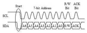
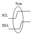
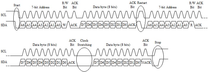
All I2C communication is started by the master device by it doing an I2C start on the bus, pulling the SDA pin low while both pins are high and then pulling the SCL pin low. Generally there is only one master device on the bus, however there is a multi-master version of the I2C protocol which is beyond the scope of this article. Next the master clocks out the address bits, there is a 7-bit address and 10-bit address protocol, 7-bit addresses are typically used in microcontroller applications so this article will focus on them. After the 7-bit address has been clocked, the read/write bit is clocked out by the master. If the read/write bit is pulled low the master is writing data to the slave and if it is high, the master is reading data from the slave. Finally following the read/write bit the master will clock in the acknowledge (ACK) bit. If a slave device acknowledges the address it will pull the SDA pin low during the ACK bit, or if no slave device acknowledges the address the SDA pin will be left to float high during the ACK bit. The following is a diagram showing what the I2C start and address bytes look like:
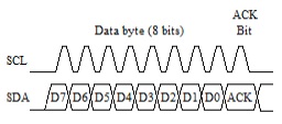
Assuming a slave device acknowledges the address byte the master will then clock out or clock in the data bytes. This is done by the master clocking 8 data bits followed by an ACK bit. If the master is writing data to the slave device, the master controls the SDA pin during the 8 data bits and the slave controls the SDA pin during the ACK bit. If the slave acknowledges the data byte it will pull the SDA pin low during the ACK bit and if it does not acknowledge the data byte, it will allow the SDA pin to float high during the ACK bit. If the master is reading data from the slave device the slave controls the SDA pin during the 8 data bits and the master controls the SDA pin during the ACK bit. The master uses the ACK bit during reads to signal the slave device if it will be reading more data or not, the master pulls the SDA pin low during the ACK if it has more data to read from the slave device and lets the SDA pin float high during the ACK if it done reading data from the slave device. The following is a diagram showing what the I2C data read and write bytes look like:
When the master is finished read or writing data it does an I2C stop to indicate that it is done communicating with the device. The master should also do an I2C stop any time the slave device does not pull the SDA line low during the ACK bit when the slave device is controlling the SDA line. The I2C stop is done by transitioning the SDA line from a low to high when the SCL line is already high. The following is a diagram showing what the I2C stop looks like:
A couple other features to know about the I2C protocol is and I2C restart or repeated start and clock stretching. The I2C restart is done by the master first setting the SDA line high then letting the SCL line go high and then pulling the SDA line low again. The restart is used in cases were a master is reading or writing data to or from a slave device and then wants to switch the operation it is doing for the same slave device. An example of when a restart may be used is when reading data from a random address from an external EEPROM, the master would first write data to the EEPROM to set the address in the EEPROM memory it wants to read from and then do a read to read the data from that address.
Clock stretching is used by the slave device to pause the master from clocking data to or from the slave device. The slave device preforms clock stretching by pulling the SCL line, when it ready for the master to resume clocking it will release the clock allowing it to float high. An example of when clock stretching may be used is when multiple bytes of data are being read from a slave device, the slave device may need to pause the master so it can load the data to be read before the master starts trying to clock it out. The following is a diagram depicting theses two features:
The CCS C Compiler has a built-in library for doing I2C communication, that library is capable of doing both a SW implementation or using the PIC ® microcontroller's HW peripheral for doing the communication as well as being a Master or Slave device.
Slave mode is only supported when using the PIC ® microcontroller's HW peripheral. Most PIC10, PIC12, PIC16 and PIC18 devices have one or in some case two Synchronous Serial Port (SSP) modules which can be used for I2C communication. The SSP module is a combined SPI and I2C peripheral that can be configured to do either SPI or I2C communication. The CCS C Compiler's #use library(), when the correct parameters are passed to it, will setup the SSP modules for I2C communication. When setup as a Master device the i2c_start(), i2c_write(), i2c_read() and i2c_stop() are used to perform the I2C communication. When setup as a Slave device the SSP interrupt and i2c_isr_state(), i2c_read() and i2c_write() functions are used for the I2C Communication, see ex_slave.c for an example of setting up slave communication. The following is an example showing how a Master would read a random byte from an external EEPROM:
#use i2c(I2C1, MASTER, fast, stream=EEPROM_STREAM)
int8 rAddress;
int8 rValue;
i2c_start(EEPROM_STREAM);
i2c_write(EEPROM_STREAM, 0xA0);
i2c_write(EEPROM_STREAM, rAddress);
i2c_start(EEPROM_STREAM);
i2c_write(EEPROM_STREAM, 0xA1);
rValue = i2c_read(EEPROM_STREAM, 0);
i2c_stop(EEPROM_STREAM);
Some newer PIC18 devices, the PIC18F47K42 family for example, have a new dedicated I2C peripheral for doing I2C communication. When setting up one of these new devices as a Slave, everything is basically the same the only exception is the ISR that is used, see ex_i2c_slave_k42.c for an example. When setting up one of the these new devices as a Master on the other hand things are different. The reason of this is that the new dedicated I2C module works differently then the SSP module did. The main difference is that old SSP module had individual bit for doing a start, restart, stop, etc. The new dedicated I2C module do not have these, instead there are registers to set the address to send set the number of bytes transfer, whether is writing or reading data, etc. All the I2C communication is handled by the peripheral, doing the start, restart, stop, etc. Because of this the CCS C Compiler legacy I2C function are not compatible with these device when setup as a Master and using the HW peripheral. So in order to use the HW I2C peripheral on these devices, the i2c_transfer(), i2c_transfer_out() and i2c_transfer_in() functions were added to the #use i2c() library. The i2c_transfer() function is used to both write and read data to and from a slave device, doing a restart between the write and read. The i2c_transfer_out() function can be used to write data to a slave device, and the i2c_transfer_in() function can be used to read data from a slave device. See ex_i2c_master_hw_k42.c for an example of their use. Also these new functions were made compatible with all other PIC ® microcontrollers both when using a software implementation or using the HW peripheral, so code written using these new functions will work on all PIC microcontrollers. The following are examples showing how a Master would read a random byte from an external EEPROM using the i2c_transfer() functions:
#use i2c(I2C1, MASTER, fast, stream=EEPROM_STREAM)
int8 rAddress;
int8 rValue;
i2c_transfer(EEPROM_STREAM, 0xA0, &rAddress, 1, &rValue, 1);
//Does - Start, Write, Restart, Read and Stop
// or
i2c_transfer_out(EEPROM_STREAM, 0xA0, &rAddress, 1);
//Does - Start, Write and Stop
i2c_transfer_in(EEPROM_STREAM, 0xA0, &rValue, 1);
//Does - Start, Read and Stop
PIC24, dsPIC30 and dsPIC33 devices have a dedicated I2C module for doing the I2C communication. Their dedicated I2C module is similar to the SSP module and all the function used for the master and slave communication are the same, including the the new i2c_transfer() functions. The only exception to this is the ISR that is used for slave communication, see ex_slave_pcd.c for an example of slave I2C communication on these device.
Like us on Facebook. Follow us on Twitter.
About CCS:
CCS is a leading worldwide supplier of embedded software development tools that enable companies to develop premium products based on Microchip PIC ® MCU and dsPIC ® DSC devices. Complete proven tool chains from CCS include a code optimizing C compiler, application specific hardware platforms and software development kits. CCS' products accelerate development of energy saving industrial automation, wireless and wired communication, automotive, medical device and consumer product applications. Established in 1992, CCS is a Microchip Premier 3rd Party Partner. For more information, please visit https://www.ccsinfo.com.
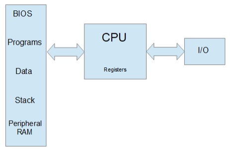
PIC ® MCU, MPLAB ® IDE, MPLAB ® ICD2, MPLAB ® ICD3 and dsPIC ® are registered trademarks of Microchip Technology Inc. in the U.S. and other countries. | January 25, 2021 Expand to read article below A common question asked is why code written for a PC cannot be used on microcontrollers. When running a program on a x86 style PC, the program is loaded into memory and begins executing. When that program needs data, it allocates more memory in the same RAM address space. Even the ROM BIOS, video RAM and more, is all in the same address space differentiated only by its address. The PC does have a second separate address space for I/O usually only used to communicate with peripherals.
On a PIC ® MCU the memory is different. There are two buses, one for program memory and the other for RAM, peripherals and special registers. That means there are two address 0's. A 0 in program memory and the other in RAM. This is referred to as a Harvard architecture.
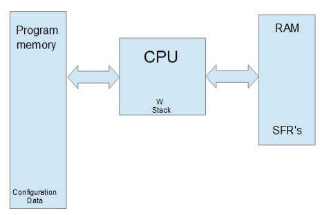
Note that the buses on each side of the above diagram are different data width sizes. On the left, is 12,14,16 or 24 bits depending on the PIC ® MCU. On the right it is 8 or 16 bit. One advantage to this architecture is both memory spaces can be accessed at the same time.
Look at the following C:
char s[10];
strcpy(s,"Hi There");
On a PC the "Hi There" is loaded with the program into memory. The s is allocated to another area of the RAM. For example if "Hi There" starts at location 0x1108 and s is allocated at 0x2004. The function call looks like this:
strcpy(0x2004, 0x1108);
On a PIC ® MCU, by default the "Hi There" is in program memory, such as 0x108. s is in the RAM address space like maybe 0x34. The call would look like this:
strcpy(0x34, 0x108);
The problem is how does strcpy() know if 0x108 is in the program memory space or RAM space? Remember there is a 0x108 address in both.
This problem can come up whenever a pointer is used. In the CCS C compiler the following syntax is used to declare pointers. ROM refers to the left side memory above and RAM to the right side.
char id; id is stored in RAM
char * id; id is stored in RAM, is a pointer to RAM
rom char id; id is stored in ROM
char rom * id; id is stored in RAM, is a pointer to ROM
char * rom id; id is stored in ROM, is a pointer to RAM
rom char * rom id; id is stored in ROM, is a pointer to ROM
Consider this declaration:
char * a;
char rom * b;
When the compiler encounters *a in the code it uses the address in a and grabs data from the RAM address space (right side). When the compiler encounters *b in the code, it uses the address in b and grabs data from the ROM address space (left side). The following would cause nothing but trouble:
a=b;
For function calls the parameters act like assignments so care must be taken not to mix pointers from different address spaces. The same kind of care is not needed on some other architectures like PC's and that is why some ported code does not work.
Back to the strcpy() the reason it works in the CCS compiler is there are two overloaded functions defined like this:
strcpy( char * dest, char * src);
strcpy( char * dest, char rom * src);
In the above example, the second function was called. Not all compiler functions have multiple versions defined. For example, there is only one version of strcat() defined, for RAM only pointers. This can be annoying if your code uses both RAM and constant strings in function calls. One way around this is to always pass RAM strings like this:
write_to_log(char * string);
...
char temp[10];
strcpy(temp, "Hi There");
write_to_log(temp);
The compiler has a feature where you can tell it to always copy constant strings to a temporary RAM area and then pass the RAM pointer. Here is how it looks:
#device pass_strings=in_ram
...
write_to_log(char * string);
...
write_to_log("Hi There");
Users need to be careful because the same RAM area is used the next time a function call is made where it needs it, so the pointer is only valid until the next call.
For some users the rom keyword above may seem new. A common approach to putting data in rom is like this:
const char message[10] = "Hi There";
By default, the compiler saves message in ROM, however, the format is not straightforward. Depending on the chip, the format is different so the data can be saved in the most efficient way possible. That saves memory, however users can not create pointers to const data. In the above users can do message[i] but not &message.
This can cause trouble porting code from other architectures so the compiler provides an alternative interpretation of const. In ANSI C const data is in RAM and the compiler throws an error if you try to change the data. To get that in CCS C do this:
#device const=read_only
As for the default const data the format varies depending on the chip and sometimes the data itself. For example, on some chips the assembly equivalent of this is used:
char lookup_const123(int index) {
switch(index) {
case 0 : return 'H';
case 1 : return 'i';
case 2 : return ' ';
case 3 : return 'T';
case 4 : return 'h';
case 5 : return 'e';
case 6 : return 'r';
case 7 : return 'e';
case 8 : return 0; } }
On a 14 bit PIC ® MCU, if the constant data is all under 128, then two items can be packed into each 14 bit word. On a 24 bit part we can pack in 3 bytes of data in each word. None of these methods can provide an ANSI compliant pointer. When the rom is used, the data is always saved with one item per pointer value so pointers are fully supported. Users should be aware on 24 bit parts rom also gets packed three bytes per instruction. Instructions take two addresses. The compiler does an internal translation from a byte address to the device address.
Be aware, although the pointer works as it should, users should not expect to use the pointer for something other than allowing the compiler to access the data.
This article covered the two major address spaces used by the CCS C compiler. The compiler also allows for user defined address spaces. That will be covered in detail in part 2 of this article. Part 3 will cover PIC ® MCU chips that have multiple ways of configuring their address space.
Like us on Facebook. Follow us on Twitter.
About CCS:
CCS is a leading worldwide supplier of embedded software development tools that enable companies to develop premium products based on Microchip PIC ® MCU and dsPIC ® DSC devices. Complete proven tool chains from CCS include a code optimizing C compiler, application specific hardware platforms and software development kits. CCS' products accelerate development of energy saving industrial automation, wireless and wired communication, automotive, medical device and consumer product applications. Established in 1992, CCS is a Microchip Premier 3rd Party Partner. For more information, please visit https://www.ccsinfo.com.
PIC ® MCU, MPLAB ® IDE, MPLAB ® ICD2, MPLAB ® ICD3 and dsPIC ® are registered trademarks of Microchip Technology Inc. in the U.S. and other countries. |
|


