August 31, 2021  Expand to read article below Expand to read article belowThe .sym compiler output file provides a good overview of the build. When you archive your source code and hex file saving the .sym file as well can be helpful. The .sym file has the following information:
RAM allocation
ROM allocation
User memory space allocation (when needed)
Source file list with CRC's
Object signatures
Unit list
Compiler settings that affect compilation
Task scheduling (when needed)
Output file list
RAM allocation
000 @SCRATCH
001 @SCRATCH
001 _RETURN_
002 @SCRATCH
003 @SCRATCH
004-007 main.a
008-00B main.b
00C-00F main.x
010-013 @ADDFF.P1
010 @PRINTF_X_809.P2
010 @delay_ms1.P3
The RAM locations are listed in order with the allocated variable names. Names with an @ before them are compiler generated variables. The main.a notation is used to indicate a local variable x in the function main(). A range indicates multiple bytes for example 004-007 is a four byte variable. For compiler built in functions frequently the .P1, .P2 notation is used for parametter 1 and 2.
Notice there are three variables all sharing location 010. This is because those three functions are never active at the same time so they can use the same memory location.
If there is a out of RAM error, the .sym file is still created and variables that will not fit in memory will have "na" instead of an address.
ROM allocation
000322 USB_CLASS_DESCRIPTORS.call
00032E USB_CLASS_DESCRIPTORS.data
000336 USB_DEVICE_DESC.call
000342 USB_DEVICE_DESC.data
000392 usb_clear_isr_reg
0003A0 usb_cdc_init
Again each area of ROM used is listed with the function or data name. Notice the data areas are shown as .call and .data. The .call address is the function that is called to retrieve data and the actual data is saved at the .data address. The .lst file will show the actual ROM data for each allocated area.
User memory space allocation (when needed)
User Memory space: eeprom
007FFE-007FFE signature
007FFC-007FFC productid
007FF6-007FFA serialnumber
User memory can be anywhere the read/write algorithm and address range are defined in the code. This shows a memory space called "eeprom" and the data areas defined.
Source file list with CRC's
Project Directory:
D:Projects
Project Files:
ex_usb_bootloader.c [05-Jul-18 12:26 CRC=4EE7C16D]
..feex_usb_common.h [26-Jan-17 17:12 CRC=79BAE87A]
..fh24FJ256GB206.h [14-Apr-21 15:34 CRC=A1FBF743]
..feusb_bootloader.h [01-Apr-19 11:57 CRC=A5BB5FCA]
..feusb_cdc.h [01-Apr-19 11:39 CRC=D21D1DD7]
The project files are listed relative to the show project directory. The file date/times are shown along with the file CRC. This can be valuable in comparing builds on different machines to make sure the right source files are being used. This data is one reason to save the .sym files to ensure future builds are done right.
Object signatures
Source signature=0C7E5CD2
Program memory checksum=0000
Hex file CRC=9AF1
More data to compare builds. Note that is you use #rom xxx=checksum then the program memory will be 0 because it saves the checksum itself at location xxx.
Unit list
Units:
project_mcu (main)
D:Projectsmcureport_mcu.o
D:Projectsmcufilter_mcu.o
D:Projectsmcumain_mcu.o
For a single compilation unit program only one file will be listed here, your main program. Above is an example of a three unit program.
Compiler settings that affect compilation
Compiler Settings:
Processor: PIC18F6722
Pointer Size: 16
ADC Range: 0-255
Opt Level: 9
Short,Int,Long: UNSIGNED: 1,8,16
Float,Double: 32,32
ICD Provisions: Yes
This section shows key compiler settings that can affect the compilation. Some lines are only shown if they are different from the compiler default.
Task scheduling (when needed)
Task Info:
Ticks: 100 ns
Cycle: 100 ms
Tasks:
The_first_rtos_task
The_second_rtos_task
The_third_rtos_task
Task Schedule:
100 ms 640:The_second_rtos_task
100 ms 643:The_third_rtos_task
Sync to next 100 ms
100 ms 633:The_first_rtos_task
100 ms 643:The_third_rtos_task
Sync to next 100 ms
100 ms 643:The_third_rtos_task
Sync to next 100 ms
100 ms 643:The_third_rtos_task
Sync to next 100 ms
100 ms 643:The_third_rtos_task
Sync to next 100 ms
100 ms 640:The_second_rtos_task
100 ms 643:The_third_rtos_task
Sync to next 100 ms
100 ms 643:The_third_rtos_task
Sync to next 100 ms
100 ms 643:The_third_rtos_task
Sync to next 100 ms
100 ms 643:The_third_rtos_task
Sync to next 100 ms
100 ms 643:The_third_rtos_task
Sync to next 100 ms
This shows a deterministic RTOS build with a 100ms time slice and timer resolution of 100ns. There are three tasks shown and the schedule of what happens in each 100ms time slice.
Output file list
Output Files:
XREF file: ex_usb_bootloader.xsym
Errors: ex_usb_bootloader.err
Ext Symbols: ex_usb_bootloader.esym
INHX8: ex_usb_bootloader.hex
Symbols: ex_usb_bootloader.sym
List: ex_usb_bootloader.lst
Debug/COFF: ex_usb_bootloader.cof
Project: ex_usb_bootloader.ccspjt
Call Tree: ex_usb_bootloader.tre
Each file created by the compiler is shown again relative to the project directory. Note that the .ccspjt file is both an input and output file. The .xsym and .esym files are only created when compiling in the IDE and those files are only used by the IDE.
Like us on Facebook. Follow us on Twitter.
About CCS:
CCS is a leading worldwide supplier of embedded software development tools that enable companies to develop premium products based on Microchip PIC ® MCU and dsPIC ® DSC devices. Complete proven tool chains from CCS include a code optimizing C compiler, application specific hardware platforms and software development kits. CCS' products accelerate development of energy saving industrial automation, wireless and wired communication, automotive, medical device and consumer product applications. Established in 1992, CCS is a Microchip Premier 3rd Party Partner. For more information, please visit https://www.ccsinfo.com.
PIC ® MCU, MPLAB ® IDE, MPLAB ® ICD2, MPLAB ® ICD3 and dsPIC ® are registered trademarks of Microchip Technology Inc. in the U.S. and other countries. | August 2, 2021 Expand to read article below The Capture Compare (CCP) peripheral of the PIC16 and PIC18 PIC® MCUs and the Input Capture (IC) peripheral of the dsPIC and PIC24 PIC® MCUs allow the MCU to capture and hold a timer value when a specific input pin reaches a user defined state. This peripheral is useful for measuring the duration between events, or determining the frequency or duty cycle of an incoming signal. This peripheral operates independent of the MCU operation, meaning it can trap the timer on the input signal without the developer having to block code execution waiting for the input signal to happen.
Version 5 of the CCS C Compiler has added a #use capture() library that makes it easy to use the CCP or IC peripheral. The API for this library provides an easy to use method for using and configuring the peripheral and timers, while also being portable from one PIC® MCU device to another. Here is an example of its use:
#use capture(CCP1, input=PIN_C2, capture_rising, stream=CAPTURE1)
unsigned int16 WaitForEvent(void)
{
while(!get_capture_event(CAPTURE1));
return(get_capture_time(CAPTURE1));
}
#use capture() configures a CCP or IC peripheral for use, and by using the STREAM option several peripherals can be configured with several instances of #use capture(). #use capture() also provides a method of configuring the timer peripheral to use and the tick rate of the timer. Several other configuration options exist, see the compiler help manual for documentation.
get_capture_event() returns TRUE if the CCP or IC peripheral has trapped an event that can be read, and get_capture_time() returns the time the event happened.
The CCS C Compiler provides an example of using this library, ex_use_caputure.c which can be found in the examples directory of the CCS C Compiler. This example can be used on any PCM, PCH or PCD version 5 CCS C Compiler.
Like us on Facebook. Follow us on Twitter.
About CCS:
CCS is a leading worldwide supplier of embedded software development tools that enable companies to develop premium products based on Microchip PIC® MCU and dsPIC® DSC devices. Complete proven tool chains from CCS include a code optimizing C compiler, application specific hardware platforms and software development kits. CCS' products accelerate development of energy saving industrial automation, wireless and wired communication, automotive, medical device and consumer product applications. Established in 1992, CCS is a Microchip Premier 3rd Party Partner. For more information, please visit https://www.ccsinfo.com.
PIC® MCU, MPLAB® IDE, MPLAB® ICD2, MPLAB® ICD3 and dsPIC® are registered trademarks of Microchip Technology Inc. in the U.S. and other countries. | August 2, 2021 Expand to read article below Easily setup your PIC® MCU clock with #use delay(). This article takes a deeper look at how to set the various oscillator fuses and oscillator registers to get the clock speed specified in #use delay(). Projects get a jump start with #use delay() accepting simple keywords: CRYSTAL, OSCILLATOR, INTERNAL and RC in addition to, or in place of, the keyword CLOCK to setup the clock.
By using one of these keywords with the clock, speed causes the compiler to set the appropriate oscillator related configuration fuses and registers to automatically achieve the specified speed with the specified clock source. The following #use delay() examples demonstrate how to set up the PIC® MCU to run at 8MHz from an external crystal and at 4MHz from the internal oscillator:
#use delay(clock=8MHz, crystal)
#use delay(crystal=8MHz) //same as above line
#use delay(clock=4MHz, internal)
#use delay(internal=4MHz) //same as above line
Devices that have a PLL, the #use delay() has an easy mechanism for setting up the PIC® MCU to run from use of it. This is easily done by setting the CLOCK option to the PLL clock speed and the CRYSTAL or OSCILLATOR option to the speed of the external clock source. For example, the following #use delay() line will set the clock to run at 32 MHz from an 8 MHz external oscillator using the PLL:
#use delay(oscillator=8MHz, clock=32MHz)
Devices with an USB peripheral, CCS has added the keywords USB, USB_FULL (same as USB) and USB_LOW. By using one of these keywords in #use delay() it causes the compiler to set the device's configuration fuses for the USB clock to be setup for either FULL or LOW speed. For example, the following line will set up the PIC® MCU to run at 48MHz from a 20MHz crystal and setup the USB clock for FULL speed:
#use delay(crystal=20MHz, clock=48MHz, USB_FULL)
By default, the compiler turns off the clock output that is available for some oscillator modes. If your application requires the clock output turned on, do something like this:
#use delay(internal=4MHz, clock_out)
When using the #use delay() to configure your oscillator it is not recommended to include oscillator related #fuses in your code or the use of setup_oscillator() unless you need to change the oscillator run-time.
Like us on Facebook. Follow us on Twitter.
About CCS:
CCS is a leading worldwide supplier of embedded software development tools that enable companies to develop premium products based on Microchip PIC® MCU and dsPIC® DSC devices. Complete proven tool chains from CCS include a code optimizing C compiler, application specific hardware platforms and software development kits. CCS' products accelerate development of energy saving industrial automation, wireless and wired communication, automotive, medical device and consumer product applications. Established in 1992, CCS is a Microchip Premier 3rd Party Partner. For more information, please visit https://www.ccsinfo.com.
PIC® MCU, MPLAB® IDE, MPLAB® ICD2, MPLAB® ICD3 and dsPIC® are registered trademarks of Microchip Technology Inc. in the U.S. and other countries. | June 24, 2021 Expand to read article below In standard C, basic I/O are handled by functions like getc(), putc() and printf() and the formatting of data is handled by functions like atoi(), atof(), strotul() and sprintf(). For example, reading a floating point number from the user over RS232 would require a combination of gets() followed by atof(). While CCS includes an input.c library that accomplishes many of these tasks, the input.c library uses a fixed RS232 stream and does not work with Keypad/LCD or USB without modification. CCS has added some support for the C++ stream operator to make it easier to handle routine user input and output.
One of the key features of this new feature in the CCS C Compiler is the way it automatically handles the conversion based upon the data types of the variables passed. These conversions are done automatically, no other helper functions like atof() need to be called. For example, if a variable is of float type the compiler will properly convert it from string to float on an input or convert float to string on an output.
The two new operators added are the extraction operator and the insertion operator:
Operator Symbol
Operator Name
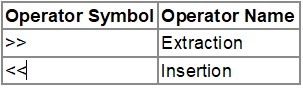
When used, these operators show the direction of data. For example:
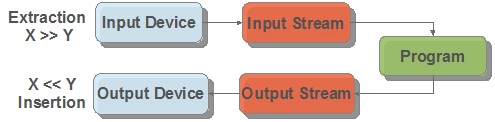
The beauty of these operators is that the x and y in the above examples can be any combination of function, RS232 serial stream, variable, string and more.
Using the stream operator for output
Simple examples:
int16 v16;
v16 = 1234;
cout << v16; // Outputs 1234
cout << hex << v16 << eoln; // Outputs 4D2 rn
Formal definition:
stream << expresion [ << expresion]...
stream in the above example can be one of the following:
* cout - maps to the default #use rs232() stream. This provides compatibility for using existing C++ code that explicitly uses the cout stream class.
* RS232 stream name - A stream identified with the stream=x option of #use rs232().
* char array (string) - Data is parsed from identifier and saved to the char array with a null terminator.
* function - A function that takes a char for it's input variable. For example, lcd_putc() in CCS's lcd.c driver or usb_cdc_putc() in CCS's usb_cdc.h driver. The function is called for each
expresion can be can be an int, float, fixed point decimal, int1 (boolean) or char array (string).
expresion can also be any of the following manipulators (from ios.h):
* hex - When converting variable to string, convert it to hex format characters (similar to %x in printf()).
* dec (default) - When converting variable to string, convert it to decimal format characters (similar to %d in printf())
* setprecision(x) - set number of places after the decimal point.
* setw(x) - set number of characters output for numbers
* boolalpha - output int1 as "true" or "false"
* noboolalpha (default) - output int1 as "1" or "0"
* fixed (default) - floating point numbers displayed in decimal format (similar to %f in printf())
* scientific - floating point numbers displayed in E notation (similar to %e in printf())
* iosdefault - all modifiers back to default settings
* endl - output CR/LF
Here is a fuller example usage of this operator:
cout << "Price is $" << setw(4) << setprecision(2) << cost*num << endl;
This example transmits "Price is $" followed by the result of cost*num with two decimal places followed by the CR/LF. This is transmitted using cout, which is the default RS232 stream.
Here is a change to the above example to display on the LCD using the lcd_putc() function provided in CCS's lcd.c driver:
lcd_putc << "Price is $" << setw(4) << setprecision(2) << cost*num << endl;
Here is a change to the above example to save the formatting to a string variable called result_string:
result_string << "Price is $" << setw(4) << setprecision(2) << cost*num << endl;
Using C++ stream operator for input
stream >> identifier [ >> identifier ]...
stream in the above example can be one of the following:
* cin - maps to the default #use rs232() stream. This provides compatibility for using existing C++ code that explicitly uses the cout stream class.
* RS232 stream name - A stream identified with the stream=x option of #use rs232().
* function - A function that returns a char. For example usb_cdc_getc() in CCS's usb_cdc.h driver.
This function is called for each character, until a r is received.
identifier can be a variable that is integer, char, char array, float or fixed point integer type. Float type formats can use the E format.
identifier can be any of the following manipulators:
* hex - hex format numbers
* dec (default) - decimal format numbers
* strspace - allow spaces to be input into strings
* nostrspace (default) - spaces terminate string entry
* iosdefault - all manipulators to default settings.
Here is an example of reading a number from the user and saving it to the variable value:
cout << "Enter Number";
cin >> value;
The above example can be quickly modified to read from the USB virtual COM port using the routines in CCS's usb_cdc.h driver:
usb_cdc_putc << "Enter Number";
usb_cdc_getc >> value;
Several values can be read at a time:
cin << variable1 << variable2 << variable3;
In the above example, the input operator would stop reading into variable1 and start reading into variable2 once a character is received that is not valid for that data type. For instance, if variable1 and variable2 are both int, it would stop reading into variable1 and start reading into variable2 upon the reception of any character that isn't "0" to "9", like a space or new-line.
Data conversion from a string to a variable can also be achieved. This example converts the str string variable to the val variable. The type of conversion is determined by the data type of val:
str >> val;
Like us on Facebook. Follow us on Twitter.
About CCS:
CCS is a leading worldwide supplier of embedded software development tools that enable companies to develop premium products based on Microchip PIC ® MCU and dsPIC ® DSC devices. Complete proven tool chains from CCS include a code optimizing C compiler, application specific hardware platforms and software development kits. CCS' products accelerate development of energy saving industrial automation, wireless and wired communication, automotive, medical device and consumer product applications. Established in 1992, CCS is a Microchip Premier 3rd Party Partner. For more information, please visit https://www.ccsinfo.com.
PIC ® MCU, MPLAB ® IDE, MPLAB ® ICD2, MPLAB ® ICD3 and dsPIC ® are registered trademarks of Microchip Technology Inc. in the U.S. and other countries. | June 24, 2021 Expand to read article below Most embedded microprocessors and microcontrollers, including the Microchip PIC® MCU families, do not contain a hardware implemented floating-point calculator. This means that all float calculations must be implemented in software using integer arithmetic, which is very resource intensive. In turn, performance heavy applications and resource limited platforms may be unable to utilize floating point numbers in their implementation. The solution for this is to instead use fixed-point arithmetic, which is simplified by the CCS C Compiler's fixed type feature.
Fixed-point arithmetic is an implementation that uses a scaling factor to represent decimal numbers in integer form. The CCS C Compiler implements this using 16 or 32 bit integers and a scaling factor of 10-n. A fixed type can be declared as follows:
int16 _fixed(n) foo; where 0 < n < 6
int32 _fixed(n) foo; where 0 < n < 11
The value n determines the number of decimal places of accuracy the variable will contain, as well as the maximum representable value. Since n is part of the type and determines what instructions are generated, it must be given as a constant at compile time.
For int16 _fixed(2) : Max = 65,535 * 10-2 = 655.35
For int32 _fixed(5) : Max = 4,294,967,295 10-5 = 42,949.67295
The binary/hexadecimal representation for any number can then be determined by multiplying by the inverse of the scaling factor and converting.
237.16 * 10-2 = 23716 = 0x5CA4
The fixed type is compatible with another fixed type of the same n for the 4 basic arithmetic operations. They are not compatible with fixed types with a different n.
int16 _fixed(1) f1 = 5.5;
int16 _fixed(1) f2 = 2.5;
f1 + f2; //evaluates to 8.0
f1 - f2; //evaluates to 3.0
f1 * f2; //evaluates to 13.7
f1 / f2; //evaluates to 2.2
It can also perform arithmetics with literals and cast integers.
int16 _fixed(2) f1 = 22.14;
int16 i1 = 7;
f1 + 19.52; //evaluates to 41.66
f1 - (int16 _fixed(2)) i1; //evaluates to 15.14
The increment and decrement operations function the same in binary. This equates to adding or subtracting 1 times the scaling unit.
int16 _fixed(3) f1= 5.234;
f1++; //f1 = 5.235
Casting a fixed type to an integer will truncate the decimal places. This can also be used to isolate the digits after the decimal by subtracting the integer cast from the original.
int16 _fixed(2) f1 = 6.94;
int16 noDec = (int16) f1; //noDec = 6
int16 _fixed(2) decOnly = f1 - noDec; //decOnly = 0.94
The CCS C Compiler also supports using printf, sprintf, etc. with the fixed-point type using the "%w" format flag. It will print the value with no leading zeroes and digits after the decimal equal to the precision.
Code:
int16 _fixed(2) f1 = 1.5;
int16 _fixed(2) f2 = 22.78;
int16 _fixed(3) f3 = 5.21
printf("%w - %w - %w", f1, f2, f3);
Output:
1.50 - 22.78 - 5.210
Floating-point numbers have an inescapable error when representing decimal in which expressions that should evaluate to be equal will be off at a very low decimal point. This happens because some decimal numbers in base10, such as 0.1, cannot be perfectly represented in base2, thus causing a rounding error. This is similar to how 1/3 cannot be represented in base10 and is then rounded to 0.33... to whatever precision is needed. Since the CCS C Compiler's implementation of fixed-point uses a decimal scalar, there is 100% precision in base10. This makes it perfect for handling money and other values where this precision is necessary.
Fixed-point operations yield significant performance increases over floating-point. In order to quantify this, benchmarks were performed using a PIC18F45K22 and the CCS C Compiler. One of the on-chip timers was used to approximate the amount of time an arithmetic operation took. For both floating-point and 16 bit fixed-point at 2 places accuracy, each operation was timed and averaged 50 times on a spread of values. The average times for each could then be compared to generalize performance.
The benchmarking results are as follows:
* Add (+): Fixed ~19.6 times faster than float.
* Subtract (-): Fixed ~19.4 times faster than float.
* Multiply (*): Float ~2.7 times faster than fixed.
* Divide (/): Fixed ~3.3 times faster than float.
The only operation that floating-point performs better is multiplication. This is logical since floats are stored in a multiplicative form (significand x baseexponent). However, fixed-point performs better on the other three, particularly on addition and subtraction.
There is also a program memory usage difference between implementing fixed-point and floatingpoint. The actual number of instructions it takes to implement the arithmetic operations is significantly different for both. The following program was compiled using both options for the PIC18F45K22.
#ifdef USE_FIXED
int16 _fixed(2) a, b, c;
#else
float a, b, c;
#endif
void main() {
a = 2.25;
b = 0.85;
c = a + b;
printf("Add: %w", c);
c = a - b;
printf("Subtract: %w", c);
c = a * b;
printf("Multiply: %w", c);
c = a / b;
printf("Divide: %w", c);
}
The compiled program's memory statistics were as follows.
Fixed Option:
* 364 instructions
* 0.84KB ROM usage
* 2.6% ROM usage
Float Option:
* 787 instructions
* 2.03KB ROM usage
* 6.3% ROM usage
Switching from the fixed implementation to float increased the instruction count by over 400. This may or may not be significant on the PIC18F45K22, depending on program complexity. However, at 32KB of ROM, it is on the higher end in terms of program memory. On the more limiting units in the PIC18 family, this would be an extremely significant amount of space or may not be significant on the PIC18F45K22, depending on program complexity. However, at 32KB of ROM, it is on the higher end in terms of program memory. On the more limiting units in the PIC18 family, this would be an extremely significant amount of space.
Like us on Facebook. Follow us on Twitter.
About CCS:
CCS is a leading worldwide supplier of embedded software development tools that enable companies to develop premium products based on Microchip PIC® MCU and dsPIC® DSC devices. Complete proven tool chains from CCS include a code optimizing C compiler, application specific hardware platforms and software development kits. CCS' products accelerate development of energy saving industrial automation, wireless and wired communication, automotive, medical device and consumer product applications. Established in 1992, CCS is a Microchip Premier 3rd Party Partner. For more information, please visit https://www.ccsinfo.com.
PIC® MCU, MPLAB® IDE, MPLAB® ICD2, MPLAB® ICD3 and dsPIC® are registered trademarks of Microchip Technology Inc. in the U.S. and other countries. | June 24, 2021 Expand to read article below If you have a version 5 compiler there is an optimization feature you may not be aware of. For many chips there is an aggressive code optimizer available, optimizing for space instead of speed. The optimizer is able to search the entire compiled program to find repeating blocks of code whereby reducing all those repeating blocks into one shared sub-routine. Optimizer is executed during the final phase of the compile which presents the ability to cross a function boundary when performing the optimization. This can only be done on parts with a flexible call instruction and available stack, for example the PIC18 and PIC24 families of devices.
This optimization level can be achieved by adding this line of code into your project.
#opt compress
The average size reduction of program memory is approximately 15%. In some cases we have seen program memory reduced by 60%. Provided below are examples of compression levels:
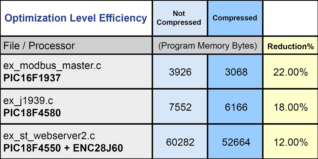
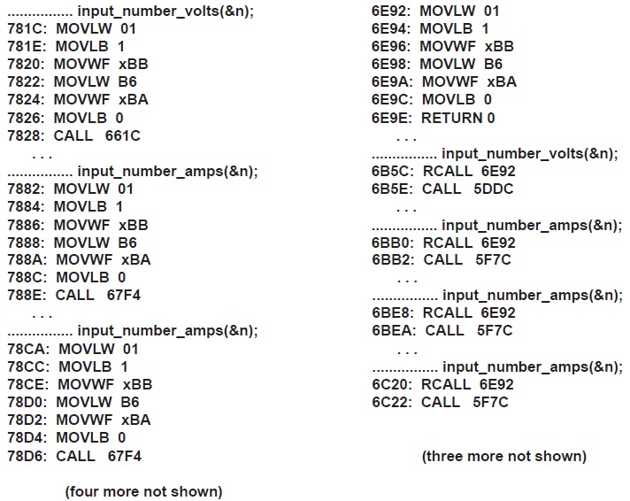
Consider this example. When a program that passes &n seven times to two functions and the code needed to do that takes 6 instructions. On the right we show the normal optimization and on the right #opt compress.
For more information on other advanced Version 5 features please visit: www.ccsinfo.com/version5
Like us on Facebook. Follow us on Twitter.
About CCS:
CCS is a leading worldwide supplier of embedded software development tools that enable companies to develop premium products based on Microchip PIC ® MCU and dsPIC ® DSC devices. Complete proven tool chains from CCS include a code optimizing C compiler, application specific hardware platforms and software development kits. CCS' products accelerate development of energy saving industrial automation, wireless and wired communication, automotive, medical device and consumer product applications. Established in 1992, CCS is a Microchip Premier 3rd Party Partner. For more information, please visit https://www.ccsinfo.com.
PIC ® MCU, MPLAB ® IDE, MPLAB ® ICD2, MPLAB ® ICD3 and dsPIC ® are registered trademarks of Microchip Technology Inc. in the U.S. and other countries. | May 17, 2021 Expand to read article below Microchip has some chips out that they call ADC2. This is the ADC module with a computational unit. In addition to legacy mode of operation, the ADC2 module can be setup in Accumulate, Average, Burst Average or Low-Pass Filter modes of operation. When setup for Accumulate mode with each trigger of the ADC, the conversion result is added to the accumulator and the ADCNT register is incremented. When setup for Average mode with each trigger of the ADC the conversion result is added to the accumulator and when the specified number of triggers has been done, the average will be preformed on the accumulator. When setup for Burst Average mode, it is similar to Average mode the difference being that when the ADC is triggered, it will perform the specified number of conversions and then perform the average calculation. When setup for Low-Pass Filter mode with each trigger of the ADC, the conversion result is sent through the filter.
To support these modes of operation, the CCS C Compiler's built-in setup_adc() function has an optional 2nd and 3rd parameter to set some parameters when using these the new modes of operation. When using Accumulate, Average or Burst Average modes the 2nd parameter sets how much the accumulated value is divided by after each conversion. When using Low-Pass Filter mode the 2nd parameter sets the cut-off frequency of the filter. The 3rd parameter to the function sets the number of samples to be done before performing a threshold comparison for Average, Burst Average and Low-Pass Filter modes of operation.
In addition to the updates to the setup_adc() function, the built-in functions adc_write() and adc_read() have been added to write and read some the other registers used by the ADC2 module. For example when setup for Low-Pass Filter mode, the filtered result is stored in the ADFLTRH and ADFLTRL registers. After the calculation is completed the adc_read() function can be then be used to read the filtered result, for example:
Result = adc_read(ADC_FILTER);
Another feature of the ADC2 module is the ability to set a trigger source to start a conversion. To support this feature the built-in function set_adc_trigger() has been added to the CCS C Compiler. For example the following can be used to setup the ADC2 module to trigger the conversion when Timer 2 period match occurs:
set_adc_trigger(ADC_TRIGGER_TIMER2);
The following is an example using the CCS C Compiler to setup and use the ADC2 module for Low-Pass Filter mode, see ex_lowpass_filter_adc2.c in the PICCExamples folder for entire example:
setup_timer_2(T2_CLK_INTERNAL | T2_DIV_BY_128, 155, 10);
//~10ms period, 100ms interrupt
setup_adc_ports(ADC_PIN, VSS_VDD);
setup_adc(ADC_LOW_PASS_FILTER_MODE | ADC_CLOCK_INTERNAL |
ADC_TAD_MUL_255 | ADC_THRESHOLD_INT_END_OF_CALCULATION,
FILTER_CUT_OFF_FREQ, ADC_READINGS);
set_adc_channel(ADC_CHANNEL);
set_adc_trigger(ADC_TRIGGER_TIMER2);
while(TRUE)
{
if(interrupt_active(INT_AD_THRESHOLD))
{
FilteredResult= adc_read(ADC_FILTER);
clear_interrupt(INT_AD_THRESHOLD); } }
Conditioning ADC data has become a standard requirement for dealing with analog voltages. Even a small amount of noise can disrupt your application. The ADC2 modules can save a lot of processing time to automate the most common filtering operations. See the ex_adc2_trigger.c example program in the compiler example directory for a full program.
Like us on Facebook. Follow us on Twitter.
About CCS:
CCS is a leading worldwide supplier of embedded software development tools that enable companies to develop premium products based on Microchip PIC ® MCU and dsPIC ® DSC devices. Complete proven tool chains from CCS include a code optimizing C compiler, application specific hardware platforms and software development kits. CCS' products accelerate development of energy saving industrial automation, wireless and wired communication, automotive, medical device and consumer product applications. Established in 1992, CCS is a Microchip Premier 3rd Party Partner. For more information, please visit https://www.ccsinfo.com.
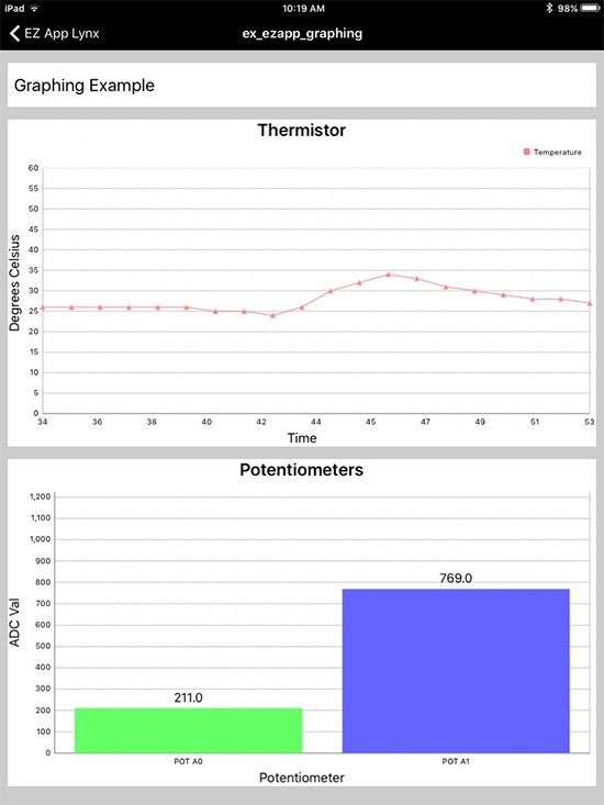
PIC ® MCU, MPLAB ® IDE, MPLAB ® ICD2, MPLAB ® ICD3 and dsPIC ® are registered trademarks of Microchip Technology Inc. in the U.S. and other countries. | May 17, 2021 Expand to read article below The EZ App Lynx compiler library, Android Application, and iOS Application can add some neat capabilities to your PIC® MCU project. With a Bluetooth® interface, this allows a user's embedded project to interface to a smart device.
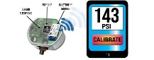
The technique used to do this does not require to write an app for the phone. In the above diagram, the micro sends the text to display on the initially blank screen. It then requests a button be put on the screen. The generic app available from CCS simply does anything the PIC ® MCU tells it to.
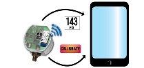
The same certified app available in the smart device stores (for free) can be used for any number of PIC ® MCU programs. Each program makes the display and operation it's own. Graphics and logs can be sent to the smart device or you can required the app download the images from the web.
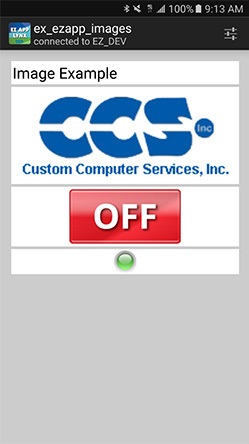
At the PIC ® MCU, a simple library is used call EZ APP LYNX and is included with all IDE compilers. An example program looks like this:
void main(void) {
ezapp_field_index_t pot;
EZAppInit(); //EZ App Lynx API
pot = EZAppAddFieldAnalogValueScaled(
"POT_A1",
EZAPP_ANALOG_TYPE_GAS_GAUGE,
0, //min
1023, //max
330, //scaling
2 //decimal points, 3.30
);
for(;;) {
EZAppTask(); //EZ App Lynx API to keep Bluetooth up
EZAppSetValue(pot, read_adc()); } }
The library has a number of buttons, indicators, sliders and much more. Here is an example inserting a background on the smart device display:
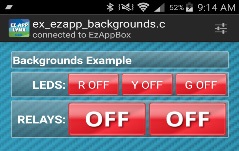
Charts and graphics are easy to do as well:
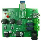
An easy way to get started is using the development kit that includes a plug in Bluetooth ® module, ready to start communicating with a smart device.
More information about EZ App Lynx, visit: http://www.ccsinfo.com/content.php?page=ez-app
Like us on Facebook. Follow us on Twitter.
About CCS:
CCS is a leading worldwide supplier of embedded software development tools that enable companies to develop premium products based on Microchip PIC ® MCU and dsPIC ® DSC devices. Complete proven tool chains from CCS include a code optimizing C compiler, application specific hardware platforms and software development kits. CCS' products accelerate development of energy saving industrial automation, wireless and wired communication, automotive, medical device and consumer product applications. Established in 1992, CCS is a Microchip Premier 3rd Party Partner. For more information, please visit https://www.ccsinfo.com.
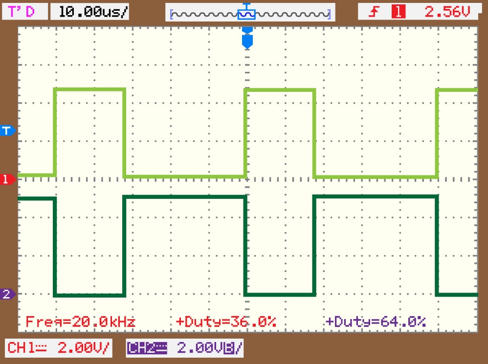
PIC ® MCU, MPLAB ® IDE, MPLAB ® ICD2, MPLAB ® ICD3 and dsPIC ® are registered trademarks of Microchip Technology Inc. in the U.S. and other countries. | May 17, 2021 Expand to read article below Pulse Width Modulation (PWM) capability was first added to the PIC® microcontroller line using the Capture/Compare/PWM (CCP) unit. Since then we have seen the enhanced CCP (ECCP) and a variety of power and motor control PWM modules each with its own features. The PWM module is called the Programmable Switch Mode Controller (PSMC). This is the most sophisticated PWM yet and is on chips like the PIC16F1789.
The PSMC allows for standard PWM, complementary PWM, shutdown control and deadband control like some of the older modules. It also allows for high resolution on the duty and frequency, as well variable frequency. It can for example do 3 phase 6 step PWM.
Input pins, comparator outputs and CCP triggers can be used not only to control shutdown, but to control if the PWM is running, or to start or stop a cycle.
Some PIC® MCU devices have as many as 4 independent units and the units can optionally be synchronized with each other.
The compiler functions are:
setup_psmc(unit, mode, period, period_time,
rising_edge, rise_time,
falling_edge, fall_time);
psmc_pins(unit, pins_used, pins_active_low);
psmc_duty(unit, fall_time);
psmc_deadband(unit, rising_edge, falling_edge);
psmc_blanking(unit, rising_edge, rise_time, falling_edge, fall_time);
psmc_shutdown(unit, option, source, pins_high);
psmc_freq_adjust(unit, freq_adjust);
psmc_modulation(unit, options);
psmc_sync(slave_unit, master_unit, options);
The following is a short example program that shows off some of the features:
#include <16f1789.h>
#use delay(osc=20mhz)
#define us(time) (int16)(time*(getenv("CLOCK")/1000000))
void main(void) {
setup_psmc(1, PSMC_ECCP_BRIDGE_FORWARD,
PSMC_EVENT_TIME | PSMC_SOURCE_FOSC | PSMC_DIV_2, us(100),
PSMC_EVENT_TIME, us(10),
PSMC_EVENT_TIME, us(35));
psmc_deadband(1, us(2), us(4));
psmc_modulation(1, PSMC_MOD_IN_PIN);
psmc_pins(1, PSMC_A | PSMC_B | PSMC_C | PSMC_D);
setup_adc(ADC_CLOCK_INTERNAL);
setup_adc_ports(sAN0);
set_adc_channel(0);
while(TRUE) {
psmc_duty(1, us(((read_adc()*(int16)10)/25)) ); } }
Other examples are included with the compiler download and begin with EX_PSMC_
Like us on Facebook. Follow us on Twitter.
About CCS:
CCS is a leading worldwide supplier of embedded software development tools that enable companies to develop premium products based on Microchip PIC ® MCU and dsPIC ® DSC devices. Complete proven tool chains from CCS include a code optimizing C compiler, application specific hardware platforms and software development kits. CCS' products accelerate development of energy saving industrial automation, wireless and wired communication, automotive, medical device and consumer product applications. Established in 1992, CCS is a Microchip Premier 3rd Party Partner. For more information, please visit https://www.ccsinfo.com.
PIC ® MCU, MPLAB ® IDE, MPLAB ® ICD2, MPLAB ® ICD3 and dsPIC ® are registered trademarks of Microchip Technology Inc. in the U.S. and other countries. | April 22, 2021 Expand to read article below DMX512 is a serial protocol that is commonly used to control stage lighting and effects. It was originally intended as a standardized method for controlling light dimmers. It soon became the primary method for linking controllers, a lighting console for example, to dimmers and special effect devices such as fog machines and intelligent lights.
A DMX512 network employs a multi-drop bus topology with nodes strung together in a daisy chain. A network consist of a single DMX512 controller, which is the master of the network and only transmitter, and one or more slave devices. Each slave device has an IN connector and usually an OUT or THRU connector, were as the controller only has an OUT connector. The controller's OUT connector is connected via a DMX512 cable to the first slave's IN connector. A second cable then links the OUT or THRU connector of the first slave to the IN connector of the next slave in the chain, and so on until all slaves are connected. The specification requires a terminator to be connected to the final OUT or THRU connector of the last slave on the daisy chain.
A DMX512 network is called a "DMX universe." The OUT connector on a DMX512 controller can control a single universe. Each universe operates up to 512 channels with each channel's parameter ranging between 0 and 255. A controller simply changes the values of these parameters.
For the DMX512 protocol, the controller transmits asynchronous serial data at 250 kbits/s. The data format is fixed at one start bit, eight data bits, and two stop bits. Each data frame consists of the following, a break, mark-after-break, slot 0 (Start Code) and up to 512 slots of channel data, each containing one byte. The break, which signals the end of one packet and the start of another, cause the slaves to start reception and also serves as a position reference for the data bytes within in the packet. The first slot, slot 0, is reserved for a start code that specifies the type of data in the packet.
The CCS C Compiler comes with a DMX512 driver, dmx.c, which can be used to develop code for either a DMX512 controller or a DMX512 slave device. When setup for a DMX512 controller the following functions are provided, DMXInit() to initialize the driver, DMXSetChannel() to set the specified channel to the specified value, DMXGetChannel() to get the current set value for the specified channel, and DMXCommit() to transmit the DMX512 channel data to the slave device. When setup for a DMX512 slave device the following functions are provided, DMXInit() to initialize the driver, DMXKbhit() to determine if new data as been received, and DMXGetd() to retrieve the DMX data.
In addition to the driver, the CCS C Compiler also provides the following two examples: ex_dmx_controller.c and ex_dma_slave.c, showing how to use the DMX512 driver to build code for a DMX512 controller and a DMX512 slave device.
Like us on Facebook. Follow us on Twitter.
About CCS:
CCS is a leading worldwide supplier of embedded software development tools that enable companies to develop premium products based on Microchip PIC® MCU and dsPIC® DSC devices. Complete proven tool chains from CCS include a code optimizing C compiler, application specific hardware platforms and software development kits. CCS' products accelerate development of energy saving industrial automation, wireless and wired communication, automotive, medical device and consumer product applications. Established in 1992, CCS is a Microchip Premier 3rd Party Partner. For more information, please visit https://www.ccsinfo.com.
PIC® MCU, MPLAB® IDE, MPLAB® ICD2, MPLAB® ICD3 and dsPIC® are registered trademarks of Microchip Technology Inc. in the U.S. and other countries. |
|


