|
This project utilizes a Hot Wheels Set, phototransistor sensor (L14F2) and a PIC16F15354 device in order to display the speed of a toy car in units of inches per second on an LED display.
Materials for the Project
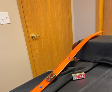
Begin a toy car and a track, such as a Hot Wheels set. Add the sensors into the track by drilling holes 4 inches apart and about 3/16ths of an inch in diameter, so the sensor fit through. It is important that these are as close to four inches apart as possible to ensure that the speeds that are determined are accurate. It is recommended the sensors have wires connected to the E and C pins, as this allows for one to bring much of the wiring away from the track, and allows for the sensors to be glued into place more easily without having to worry about a close connection to a board. Hot glue works best to mount the sensors in the holes. Make sure that the sensors are glued in low enough so that the movement of the car is not hindered by the car hitting the light sensors during its trip.
Take note that light sensors at the top of a loop may not work well if the car slightly falls off the track because it may not register the change in light.
In addition to the above materials, an in-circuit programmer unit, power source, and A to B USB and a proper connector for the device to the programmer is necessary for programming the development board.
Hardware Design
The development board has a PIC16F15354, four 7-segment LEDs to display the speed of the car after the car has passed over the two light sensors. The microcontroller has a built in timer and has six pins (B0-B5) available for the programmer, Extra pins are available to add features to the program.
The example programs only include the ability to make numbers appear on the LED display, but by adding additional entries in SEVENSEG, it would allow one to display letters as well.
The example program have the sensors to have their input return 1 (true) until they are covered up so that they are no longer exposed to light. At this point the sensor will then return 0 (false). The schematic for this sensor is illustrated below:
Program Example Code
#use timer(TIMER=2, ISR, TICK=1ms, BITS=32)
do {
speed = 0;
if (!input(PIN_B1)) {
set_ticks(0);
while(input(PIN_B3));
time = get_ticks();
travelTime = (float32) time * 3 / 1000;
speed = 12 / travelTime;
delay_ms(250); } else if (!input(PIN_B3)) {
set_ticks(0);
while(input(PIN_B1));
time = get_ticks();
travelTime = (float32) time * 3 / 1000;
speed = 12 / travelTime;
delay_ms(250); } } while (speed == 0);
This is the code that is utilized to calculate the speed based on feedback from the light sensors. The "#use timer" preprocessor directive will set up the timer that is used to calculate the speed. In order to calculate the speed for the race car, the speed is initially set to 0 at the beginning of the loop to ensure that the speed is reset. Next, it checks to see if there is input coming from either sensor. Once there is a change in the input from one of these pins, the timer will start and will wait until the second pin detects an object running over it. At that point,the variable time will be set to the value returned by get_ticks(), which indicates the time in milliseconds that it took for the car to travel from one sensor to another. Since the light sensors are spaced four inches apart, the time to travel a full foot could be calculated by multiplying this time by three, and dividing by 1000 to convert milliseconds to seconds. This is stored as a variable called travelTime. Finally, to convert from the time that it takes to travel one foot to speed in inches per second, one can take 12 divided by the variable travelTime. The speed will then be displayed on the LED display in units of inches per second. This code can display the speed no matter the direction that the car is traveling.
Compile the program and connect the ICD unit to the development board and power supply. In the Compiler ribbon, select Compile -> Build & Run to program the board. Each of the four LEDs should display a "7" since that is what the default value at the start of the program was set to. Once the sensors are tripped for the first, the LED display should change to present the speed of the car. The speed should continue to be displayed until the power is disconnected, or until both of the sensors do not receive input / do not detect light. Sensors are in electronic products that people use daily. This demonstration would be a great way to introduce to students how sensors work and embedded programming in a fun way.
Like us on Facebook. Follow us on Twitter.
About CCS:
CCS is a leading worldwide supplier of embedded software development tools that enable companies to develop premium products based on Microchip PIC® MCU and dsPIC® DSC devices. Complete proven tool chains from CCS include a code optimizing C compiler, application specific hardware platforms and software development kits. CCS' products accelerate development of energy saving industrial automation, wireless and wired communication, automotive, medical device and consumer product applications. Established in 1992, CCS is a Microchip Premier 3rd Party Partner. For more information, please visit https://www.ccsinfo.com.
PIC® MCU, MPLAB® IDE, MPLAB® ICD2, MPLAB® ICD3 and dsPIC® are registered trademarks of Microchip Technology Inc. in the U.S. and other countries.
|


