|
This is a guide to successful In-Circuit Serial Programming (ICSP). To get started, the power connections, the supply voltage, and the bypass capacitors must be suitable for the device that is being programmed. If the ICD will be used for debugging, then the target device must also have an active clock oscillator.
ICSP Cable
Excessive cable length can cause various problems such as: noise pickup, crosstalk, signal reflections, or excessive voltage drop. Be sure to use a cable that is as short as practical for the application. Keep in mind that the circuit board's trace length will add to the overall wiring length. Therefore, place the ICSP connector close to the PIC on the circuit board.
ICSPCLK/PGC (clock) and ICSPDAT/PGD (data):
These are bidirectional data lines. The circuit must be designed in a way that does not significantly alter the voltage levels, rise time, or fall time of the signals. Avoid diodes, pull-up resistors, pull-down resistors, and large value capacitors. Please see Figure 1 for an example of normal PGC (top) and PCD (bottom) signals. It is best to dedicate these pins to ICSP. If the ICD will not be used for debugging, then additional circuitry can be connected to these pins. This allows the pins to be used for other functions after programming has completed, but the circuitry must present a high impedance during programming. If the additional circuitry does not present a sufficiently high impedance, a resistor can typically be added between the PIC® MCU pin and the additional circuitry. This can minimize the undesired loading affects of the additional circuitry and allow successful programming. If a resistor is not suitable, then the circuit can include a switch or a jumper instead. After programming has been completed, the switch or jumper would be used to connect the additional circuitry to the PIC® MCU.
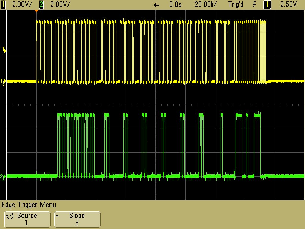
Figure 1
In general, we do not advise the use of capacitors on PGC or PGD. However, there is an exception for electrically-noisy environments and/or unusually long ICSP cables. In these situations, it can be helpful to include a 68pF capacitor from PGC to ground and a second 68pF capacitor from PGD to ground. This can help with noise suppression.
To help with design flexibility, some PIC® MCU devices have more than one pair of PGC/PGD pins. Any pair can be used for programming. There are configuration bits to select the pair that is used for debugging.
/MCLR (Master Clear, active lo)
The circuit must be designed in a way that does not significantly alter the voltage levels, rise time, or fall time of the signal during programming or debugging. In many situations, only a pull-up resistor is required here. CCS recommends a 47K pull-up resistor. Please see Figure 2 for an example of a normal /MCLR signal.
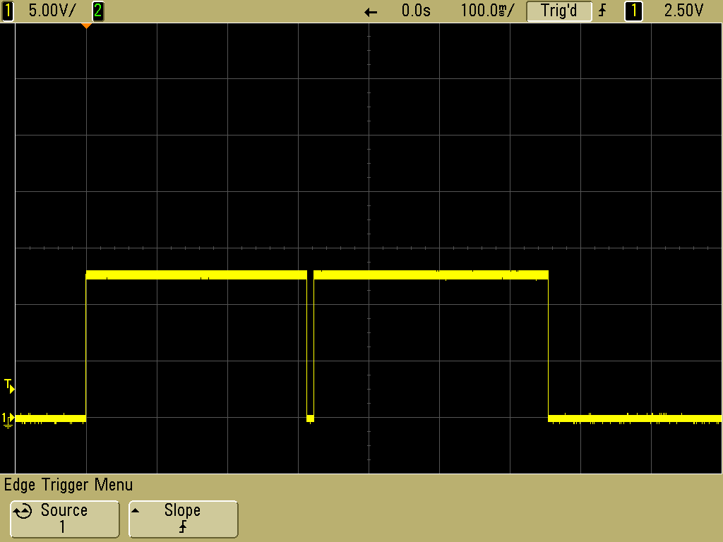
Figure 2
Many PIC® MCU devices include a Power-up Timer (PUT) which can be enabled in the device's configuration bits. For most applications, the PUT eliminates the need for a capacitor on the /MCLR pin. If a capacitor is connected between the pull-up resistor and ground, include a resistor or a diode between the capacitor and the /MCLR pin on the PIC® MCU. This will minimize the affect of the capacitor during programming / debugging. Microchip literature recommends a Schottky diode or a 470 Ohm resistor. If a Schottky diode is used, the cathode would connect to the /MCLR pin on the PIC® MCU. The /MCLR pin on the PIC® MCU will always connect directly to the /MCLR pin on the circuit board's ICSP connector when an ICD-U80 (or other CCS programmer) is used.
For some PIC® MCU devices, up to +13V is supplied to the /MCLR pin during programming. The circuit must be designed in a way that is tolerant of that voltage. The 47K pull-up resistor is a good way to deal with that voltage.
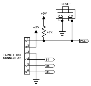
Figure 3
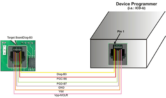
Figure 4
Help with Diag-B3, Pin 6 on Target Board ICSP Connector
During debugging, Pin 6 may be used to interact with a monitor inside of the debug window. This allows for printf()'s and getc()'s in the code to show up in the debugger. Any PIC® MCU I/O pin may be selected and the use of pin 6 is optional. Note that the CCS ICD units can also be used outside of a debugger to have this same capability with the PGC/PGD pins. In that configuration, the ICD acts like a TTL-to-serial converter.
Use of the Troubleshooting Aids on the CCSLOAD Diagnostics Tab
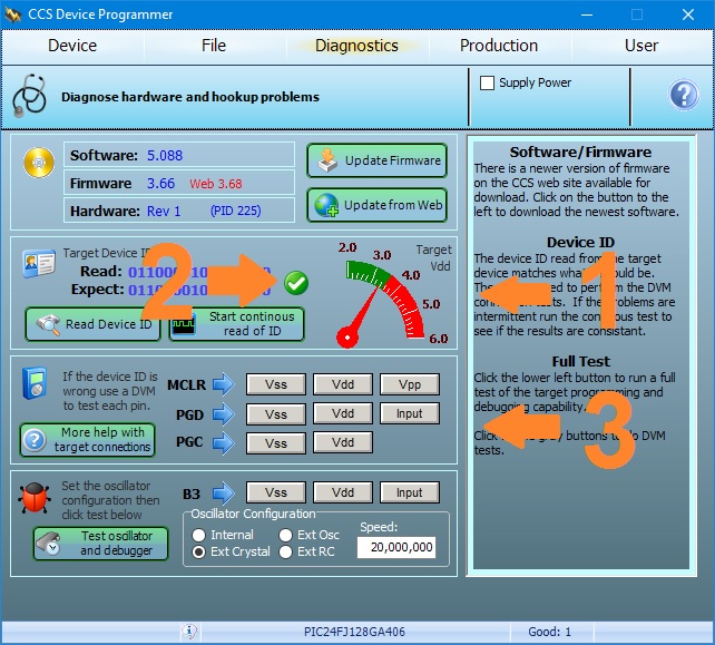
When the Diagnostics Tab is selected, the software will report the measured supply voltage in the target circuit and it will report the device ID that is read from the target device. Note: 12-bit PIC® MCU devices do not report a device ID.
1. Check the voltage on the screen to be sure it matches the target chip. If not, check the cable connections for power and verify the power source is set right.
2. Check to see if there is green checkmark indicating the device ID is right. If so, the hardware connections are likely good. To verify, click on "Start continuous read of ID" and watch the lower right to see if there are intermitent problems that may be caused by noise. If there seems to be a problem, use a scope to view the signals real time.
3. With no green checkmark, you should check the connections for PGC, PGD and MCLR using the gray buttons in the lower part of the window. Use a DVM connected directly to the chip to verify that the voltage at each pin can be changed by the software.
For additional help, please contact CCS Technical Support:
https://www.ccsinfo.com/contactEmail.php?dept=ts
References:
Microchip PICkit 2 User Guide
Microchip MPLAB PICkit 5 User Guide
Microchip In-Circuit Serial Programming (ICSP) Guide
CCS FAQ, How do I connect the ICD-S/U to my PIC® MCU hardware?:
https://www.ccsinfo.com/faq.php?page=connect_icd
Like us on Facebook. Follow us on X (Twitter).
About CCS:
CCS is a leading worldwide supplier of embedded software development tools that enable companies to develop premium products based on Microchip PIC® MCU and dsPIC® DSC devices. Complete proven tool chains from CCS include a code optimizing C compiler, application specific hardware platforms and software development kits. CCS' products accelerate development of energy saving industrial automation, wireless and wired communication, automotive, medical device and consumer product applications. Established in 1992, CCS is a Microchip Premier 3rd Party Partner. For more information, please visit https://www.ccsinfo.com.
PIC® MCU, MPLAB® IDE, MPLAB® ICD2, MPLAB® ICD3 and dsPIC® are registered trademarks of Microchip Technology Inc. in the U.S. and other countries.
|