|
The PIC16F1614 family of devices is currently the only PIC® MCU family that has a built in Math Accelerator with Proportional-Integral-Derivative (PID) Module. This module is a mathematics module that can perform a variety of operations, most prominently acting as a PID controller.
The module accomplishes the task of calculating the PID algorithm by utilizing user-provided coefficients along with a multiplier and accumulator. The main benefit of using the hardware module is for doing the PID calculation much faster than it can be done in software. For example when running the PIC® from the 32 MHz internal oscillator the built-in HW PID function was measured to take 12.8 us, compared to a software PID function which was measure to take 216 us. This is approximately 1/16 of the time.
The following are the built-in functions that have been added for the Math Accelerator with PID module:
* setup_pid() - used to setup the PID module and set the user-input coefficients.
* pid_get_result() - used to input the set point and feedback from the external system to the PID module, start the calculation, and to retrieve the result to input in the external system.
* pid_read() - used to read various PID module registers.
* pid_write() - used to write various PID module registers.
* pid_busy() - used to check if PID module is busy or not-busy, finished, with calculation.
The Math Accelerator with PID module can be setup for three basic functions PID calculation, 16-bit unsigned add and multiple and 16-bit signed add and multiple. Both of the add and multiple modes can also be setup to accumulate the output.
When setup for PID mode the user-input coefficients, K1, K2 and K3, are calculated from the three classic PID coefficients Kp, Ki and Kd with the following equations:
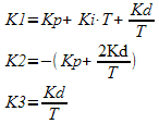
T is the sampling period.
The following is an example of how to setup and use the Math Accelerator with PID module in PID mode:
void main(void) {
pid_struct_t PIDOutput;
unsigned int16 ADCReading;
signed int16 K1 = 7, K2 = -6, K3 = 0;
unsigned int16 SetPoint = 500;
unsigned int16 PWMDuty;
setup_pid(PID_MODE_PID, K1, K2, K3);
//Setup ADC
setup_adc_ports(sAN3, VSS_VDD);
setup_adc(ADC_CLOCK_INTERNAL);
set_adc_channel(3);
//Setup PWM 3
setup_timer_4(T4_CLK_INTERNAL | T4_DIV_BY_32, 249, 1); //1ms period, from 32 MHz
set_pwm3_duty(0); //0% duty
setup_pwm3(PWM_ENABLED | PWM_OUTPUT | PWM_TIMER4);
while(TRUE) {
delay_ms(50);
ADCReading = read_adc();
pid_get_result(SetPoint, ADCReading, &PIDOutput);
PIDOutput.u &= 0x07;
if(PIDOutput.u >= 4) //PIDOutput is negative, set PWMDuty to Minimum
PWMDuty = 0; else if(PIDOutput.u != 0) //PIDOutput > Maximum, set PWMDuty to Maximum
PWMDuty = 1000; else if(PIDOutput.l > 1000) //PIDOutput > Maximum, set PWMDuty to Maximum
PWMDuty = 1000; else
PWMDuty = PIDOutput.l;
set_pwm3_duty(PWMDuty); } }
When the Math Accelerator with PID module is setup for one of the add and multiple mode the operation is preformed as follows:
OUTPUT = (A + B) * C
The multiple value, C, is set with the K1 option that is passed setup_pid() function, and the two add values, A and B, are passed as the set_point and input parameters to the pid_get_result() function. For example the following is how to setup the Math Accelerator with PID module in add and multiply mode:
int16 C = 100;
int16 A, B;
pid_struct_t Result;
//setup for add and multiple mode and set multipler
setup_pid(PID_MODE_UNSIGNED_ADD_MULTIPLY, C);
//get add and multiple result
pid_get_result(A, B, &Result);
The PIC16F1614 family of devices is available in the IDE compilers and the PCM command-line compilers starting with version 5.045. They come in 14 and 20 pin packages with flash memory of 4048 or 8192 instructions. Additionally they have four 8-bit timers, three 16-bit timers, 8 or 12 analog inputs, two CCP modules, two 10-bit PWM modules and 1 CWG module, which can be used in conjunction with other modules, CCP or PWM for example, to generate a Half-Bridge or Full-Bridge PWM.
|


