|
The I2C protocol is a very useful serial communication protocol to communicate with multiple devices using only two I/O pins of the PIC® MCU, the SCL and SDA pins. The SCL pin is the clock pin used to synchronizing the clocking of data into and out of the devices, and the SDA pin is the data pin that the data is clock into and out of the devices. Both pins are open drain configured, meaning that to output a low on one the of pins, the pin is driven low and to output a high on one of the pins, the pin is floated, requiring an external pull-up resistor to pull the line to the high voltage level.
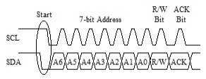
All I2C communication is started by the master device by it doing an I2C start on the bus, pulling the SDA pin low while both pins are high and then pulling the SCL pin low. Generally there is only one master device on the bus, however there is a multi-master version of the I2C protocol which is beyond the scope of this article. Next the master clocks out the address bits, there is a 7-bit address and 10-bit address protocol, 7-bit addresses are typically used in microcontroller applications so this article will focus on them. After the 7-bit address has been clocked, the read/write bit is clocked out by the master. If the read/write bit is pulled low the master is writing data to the slave and if it is high, the master is reading data from the slave. Finally following the read/write bit the master will clock in the acknowledge (ACK) bit. If a slave device acknowledges the address it will pull the SDA pin low during the ACK bit, or if no slave device acknowledges the address the SDA pin will be left to float high during the ACK bit. The following is a diagram showing what the I2C start and address bytes look like:
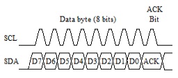
Assuming a slave device acknowledges the address byte the master will then clock out or clock in the data bytes. This is done by the master clocking 8 data bits followed by an ACK bit. If the master is writing data to the slave device, the master controls the SDA pin during the 8 data bits and the slave controls the SDA pin during the ACK bit. If the slave acknowledges the data byte it will pull the SDA pin low during the ACK bit and if it does not acknowledge the data byte, it will allow the SDA pin to float high during the ACK bit. If the master is reading data from the slave device the slave controls the SDA pin during the 8 data bits and the master controls the SDA pin during the ACK bit. The master uses the ACK bit during reads to signal the slave device if it will be reading more data or not, the master pulls the SDA pin low during the ACK if it has more data to read from the slave device and lets the SDA pin float high during the ACK if it done reading data from the slave device. The following is a diagram showing what the I2C data read and write bytes look like:
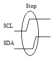
When the master is finished read or writing data it does an I2C stop to indicate that it is done communicating with the device. The master should also do an I2C stop any time the slave device does not pull the SDA line low during the ACK bit when the slave device is controlling the SDA line. The I2C stop is done by transitioning the SDA line from a low to high when the SCL line is already high. The following is a diagram showing what the I2C stop looks like:
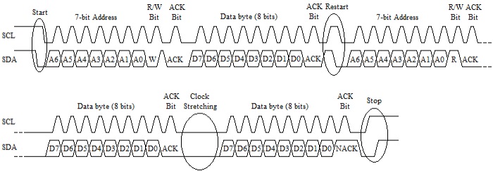
A couple other features to know about the I2C protocol is and I2C restart or repeated start and clock stretching. The I2C restart is done by the master first setting the SDA line high then letting the SCL line go high and then pulling the SDA line low again. The restart is used in cases were a master is reading or writing data to or from a slave device and then wants to switch the operation it is doing for the same slave device. An example of when a restart may be used is when reading data from a random address from an external EEPROM, the master would first write data to the EEPROM to set the address in the EEPROM memory it wants to read from and then do a read to read the data from that address.
Clock stretching is used by the slave device to pause the master from clocking data to or from the slave device. The slave device preforms clock stretching by pulling the SCL line, when it ready for the master to resume clocking it will release the clock allowing it to float high. An example of when clock stretching may be used is when multiple bytes of data are being read from a slave device, the slave device may need to pause the master so it can load the data to be read before the master starts trying to clock it out. The following is a diagram depicting theses two features:
The CCS C Compiler has a built-in library for doing I2C communication, that library is capable of doing both a SW implementation or using the PIC® microcontroller's HW peripheral for doing the communication as well as being a Master or Slave device.
Slave mode is only supported when using the PIC® microcontroller's HW peripheral. Most PIC10, PIC12, PIC16 and PIC18 devices have one or in some case two Synchronous Serial Port (SSP) modules which can be used for I2C communication. The SSP module is a combined SPI and I2C peripheral that can be configured to do either SPI or I2C communication. The CCS C Compiler's #use library(), when the correct parameters are passed to it, will setup the SSP modules for I2C communication. When setup as a Master device the i2c_start(), i2c_write(), i2c_read() and i2c_stop() are used to perform the I2C communication. When setup as a Slave device the SSP interrupt and i2c_isr_state(), i2c_read() and i2c_write() functions are used for the I2C Communication, see ex_slave.c for an example of setting up slave communication. The following is an example showing how a Master would read a random byte from an external EEPROM:
#use i2c(I2C1, MASTER, fast, stream=EEPROM_STREAM)
int8 rAddress;
int8 rValue;
i2c_start(EEPROM_STREAM);
i2c_write(EEPROM_STREAM, 0xA0);
i2c_write(EEPROM_STREAM, rAddress);
i2c_start(EEPROM_STREAM);
i2c_write(EEPROM_STREAM, 0xA1);
rValue = i2c_read(EEPROM_STREAM, 0);
i2c_stop(EEPROM_STREAM);
Some newer PIC18 devices, the PIC18F47K42 family for example, have a new dedicated I2C peripheral for doing I2C communication. When setting up one of these new devices as a Slave, everything is basically the same the only exception is the ISR that is used, see ex_i2c_slave_k42.c for an example. When setting up one of the these new devices as a Master on the other hand things are different. The reason of this is that the new dedicated I2C module works differently then the SSP module did. The main difference is that old SSP module had individual bit for doing a start, restart, stop, etc. The new dedicated I2C module do not have these, instead there are registers to set the address to send set the number of bytes transfer, whether is writing or reading data, etc. All the I2C communication is handled by the peripheral, doing the start, restart, stop, etc. Because of this the CCS C Compiler legacy I2C function are not compatible with these device when setup as a Master and using the HW peripheral. So in order to use the HW I2C peripheral on these devices, the i2c_transfer(), i2c_transfer_out() and i2c_transfer_in() functions were added to the #use i2c() library. The i2c_transfer() function is used to both write and read data to and from a slave device, doing a restart between the write and read. The i2c_transfer_out() function can be used to write data to a slave device, and the i2c_transfer_in() function can be used to read data from a slave device. See ex_i2c_master_hw_k42.c for an example of their use. Also these new functions were made compatible with all other PIC® microcontrollers both when using a software implementation or using the HW peripheral, so code written using these new functions will work on all PIC microcontrollers. The following are examples showing how a Master would read a random byte from an external EEPROM using the i2c_transfer() functions:
#use i2c(I2C1, MASTER, fast, stream=EEPROM_STREAM)
int8 rAddress;
int8 rValue;
i2c_transfer(EEPROM_STREAM, 0xA0, &rAddress, 1, &rValue, 1);
//Does - Start, Write, Restart, Read and Stop
// or
i2c_transfer_out(EEPROM_STREAM, 0xA0, &rAddress, 1);
//Does - Start, Write and Stop
i2c_transfer_in(EEPROM_STREAM, 0xA0, &rValue, 1);
//Does - Start, Read and Stop
PIC24, dsPIC30 and dsPIC33 devices have a dedicated I2C module for doing the I2C communication. Their dedicated I2C module is similar to the SSP module and all the function used for the master and slave communication are the same, including the the new i2c_transfer() functions. The only exception to this is the ISR that is used for slave communication, see ex_slave_pcd.c for an example of slave I2C communication on these device.
Like us on Facebook. Follow us on Twitter.
About CCS:
CCS is a leading worldwide supplier of embedded software development tools that enable companies to develop premium products based on Microchip PIC® MCU and dsPIC® DSC devices. Complete proven tool chains from CCS include a code optimizing C compiler, application specific hardware platforms and software development kits. CCS' products accelerate development of energy saving industrial automation, wireless and wired communication, automotive, medical device and consumer product applications. Established in 1992, CCS is a Microchip Premier 3rd Party Partner. For more information, please visit https://www.ccsinfo.com.
PIC® MCU, MPLAB® IDE, MPLAB® ICD2, MPLAB® ICD3 and dsPIC® are registered trademarks of Microchip Technology Inc. in the U.S. and other countries.
|


