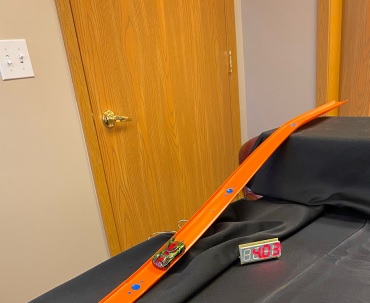
December 22, 2020  Expand to read article below Expand to read article belowThis project utilizes a Hot Wheels Set, phototransistor sensor (L14F2) and a PIC16F15354 device in order to display the speed of a toy car in units of inches per second on an LED display.
 Materials for the Project
Begin a toy car and a track, such as a Hot Wheels set. Add the sensors into the track by drilling holes 4 inches apart and about 3/16ths of an inch in diameter, so the sensor fit through. It is important that these are as close to four inches apart as possible to ensure that the speeds that are determined are accurate. It is recommended the sensors have wires connected to the E and C pins, as this allows for one to bring much of the wiring away from the track, and allows for the sensors to be glued into place more easily without having to worry about a close connection to a board. Hot glue works best to mount the sensors in the holes. Make sure that the sensors are glued in low enough so that the movement of the car is not hindered by the car hitting the light sensors during its trip.
Take note that light sensors at the top of a loop may not work well if the car slightly falls off the track because it may not register the change in light.
In addition to the above materials, an in-circuit programmer unit, power source, and A to B USB and a proper connector for the device to the programmer is necessary for programming the development board.
Hardware Design
The development board has a PIC16F15354, four 7-segment LEDs to display the speed of the car after the car has passed over the two light sensors. The microcontroller has a built in timer and has six pins (B0-B5) available for the programmer, Extra pins are available to add features to the program.
The example programs only include the ability to make numbers appear on the LED display, but by adding additional entries in SEVENSEG, it would allow one to display letters as well.
The example program have the sensors to have their input return 1 (true) until they are covered up so that they are no longer exposed to light. At this point the sensor will then return 0 (false). The schematic for this sensor is illustrated below:
Program Example Code
#use timer(TIMER=2, ISR, TICK=1ms, BITS=32)
do {
speed = 0;
if (!input(PIN_B1)) {
set_ticks(0);
while(input(PIN_B3));
time = get_ticks();
travelTime = (float32) time * 3 / 1000;
speed = 12 / travelTime;
delay_ms(250); } else if (!input(PIN_B3)) {
set_ticks(0);
while(input(PIN_B1));
time = get_ticks();
travelTime = (float32) time * 3 / 1000;
speed = 12 / travelTime;
delay_ms(250); } } while (speed == 0);
This is the code that is utilized to calculate the speed based on feedback from the light sensors. The "#use timer" preprocessor directive will set up the timer that is used to calculate the speed. In order to calculate the speed for the race car, the speed is initially set to 0 at the beginning of the loop to ensure that the speed is reset. Next, it checks to see if there is input coming from either sensor. Once there is a change in the input from one of these pins, the timer will start and will wait until the second pin detects an object running over it. At that point,the variable time will be set to the value returned by get_ticks(), which indicates the time in milliseconds that it took for the car to travel from one sensor to another. Since the light sensors are spaced four inches apart, the time to travel a full foot could be calculated by multiplying this time by three, and dividing by 1000 to convert milliseconds to seconds. This is stored as a variable called travelTime. Finally, to convert from the time that it takes to travel one foot to speed in inches per second, one can take 12 divided by the variable travelTime. The speed will then be displayed on the LED display in units of inches per second. This code can display the speed no matter the direction that the car is traveling.
Compile the program and connect the ICD unit to the development board and power supply. In the Compiler ribbon, select Compile -> Build & Run to program the board. Each of the four LEDs should display a "7" since that is what the default value at the start of the program was set to. Once the sensors are tripped for the first, the LED display should change to present the speed of the car. The speed should continue to be displayed until the power is disconnected, or until both of the sensors do not receive input / do not detect light. Sensors are in electronic products that people use daily. This demonstration would be a great way to introduce to students how sensors work and embedded programming in a fun way.
Like us on Facebook. Follow us on Twitter.
About CCS:
CCS is a leading worldwide supplier of embedded software development tools that enable companies to develop premium products based on Microchip PIC ® MCU and dsPIC ® DSC devices. Complete proven tool chains from CCS include a code optimizing C compiler, application specific hardware platforms and software development kits. CCS' products accelerate development of energy saving industrial automation, wireless and wired communication, automotive, medical device and consumer product applications. Established in 1992, CCS is a Microchip Premier 3rd Party Partner. For more information, please visit https://www.ccsinfo.com.
PIC ® MCU, MPLAB ® IDE, MPLAB ® ICD2, MPLAB ® ICD3 and dsPIC ® are registered trademarks of Microchip Technology Inc. in the U.S. and other countries. | December 22, 2020 Expand to read article below Recent versions of the Linux 32 bit LIBC library running on 64 bit machines have caused our compiler to crash with a segmentation fault. The problem started with version 2.28 of the library. You can find your version under Linux with this command:
ldd --version
Users running on a 64 bit machine who keep their Linux kernel up to date have noticed the problem. The root of the problem is when the compiler launcher (ccsc) loads the compiler dynamic library (like pcm.so) memory is corrupted. We think, but can not be sure, the newer versions of the library loader assume the code segments are aligned on 64 bit boundaries even if the library is 32 bit.
CCS has been working on a number of fronts to find a solution that will work on everyone's system. The only success we have had is to compile, the compiler to generate 64 bit code. Since this changes all our internal data types we have needed to undertake a lot of testing to ensure the compiler is sound.
The new Linux software will be available before Christmas.
This means that there will be 32 bit and 64 bit downloads for the Linux compilers. The 32 bit will work on all 32 bit systems and the older 64 bit systems. The 64 bit version will work on all 64 bit systems.
Any Linux download rights that expired in 2020 have had a year of download rights added to their account. Contact support if you need new registration files.
Like us on Facebook. Follow us on Twitter.
About CCS:
CCS is a leading worldwide supplier of embedded software development tools that enable companies to develop premium products based on Microchip PIC ® MCU and dsPIC ® DSC devices. Complete proven tool chains from CCS include a code optimizing C compiler, application specific hardware platforms and software development kits. CCS' products accelerate development of energy saving industrial automation, wireless and wired communication, automotive, medical device and consumer product applications. Established in 1992, CCS is a Microchip Premier 3rd Party Partner. For more information, please visit https://www.ccsinfo.com.
PIC ® MCU, MPLAB ® IDE, MPLAB ® ICD2, MPLAB ® ICD3 and dsPIC ® are registered trademarks of Microchip Technology Inc. in the U.S. and other countries. | December 22, 2020 Expand to read article below There are many version control programs available to help keep track of software changes from one version to another as well as shared code between projects. We use a free SVN here at CCS, but there are many good free and commercial products out there. This article addresses how to best use features in the CCS compiler tool suite to augment the basic capabilities of a version control system.
One problem that frequently comes up is attempting to rebuild a project that was built years ago. This is usually done before making an update to make sure the right code is being used as a starting point. Sometimes users even have trouble getting the same build result on different PC's even using the current software. There are three considerations for getting an exact hex file from source:
1. Compiler Version
Optimization changes are made in almost every release, although the software may be functionally the same, the hex file can be different. If it is important that the hex file is identical, then including code like the following in the source will help:
#if (getenv("VERSION_STRING") != "5.045")
#error Wrong compiler version, use 5.045
#endif
Users should also archive the compiler installer for that version. If it is lost, users can always contact CCS with the reference number, compiler name (like PCW) and the version needed.
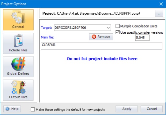
The IDE compiler allows for multiple versions to be available at the same time. Users can also fix the version for a specific project under OPTIONS > PROJECT OPTIONS so the IDE will always use that version for that project.
If there is a difference in builds between versions users can use the IDE feature TOOLS > FILE COMPARE to compare the old and new .lst files. This will identify all differences in the generated code. A review of the differences should help deciding if there is cause for concern. It is always a good idea to archive the .lst file with the source to help in this analysis. Note that the compiler version is at the top of the .lst file.
2. Include Files
It is important to use the same include files to get the same result. It is best to archive all include files used for a project, including those provided by the compiler in the version control system. This is usually the cause of a program compiling differently between two PC's. The compiler has an output file that can help users identify all the included files and the exact file being used. In the .sym file there will be a section that looks like this:
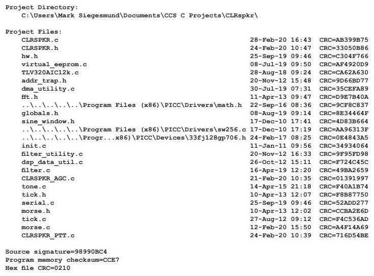
Under "Project Files" is listed every source file used to build the project along with the file date of the source file and its CRC. The files are relative paths with respect to the project directory shown above the list. This is a great help in making sure all the include files have been archived and that the same files are being used for a build. Archiving the .sym file will help in figuring out what was done.
Notice the .sym file also includes a CRC of the entire source code base and a CRC of the hex file. The CRC shown in the .sym file will match the CRC shown at the end of the .hex file. Users can open the .hex file in notepad to check it. The CCS device programmers will users if the hex file itself does not match the CRC due to a corrupted file.
3. Changes Outside the Source Code
There are a few things that can affect the generated code outside of the source code. The most obvious is compiler switches that might be included on the command line for a command line compile or from MPLAB. For example optimization level. The CCS IDE does not have code generation options as we encourage users to include such options in the source code (like: #opt 5).
Pre-processor defines can also be included on the command line or in the IDE under global defines. This is a great way to use the same code to produce different versions of the firmware. In the CCS IDE saving the .ccspjt file will have those defines saved. For command line compiles, saving the batch file that does the compiles might be enough. Users can also insert comments in the hex file to indicate what defines were used. For example:
#hexcomment\ Built with CCS PCD Compiler version __PCD__
#ifdef HAS_PTT
#hexcomment\ Built with "HAS_PTT" defined
#endif
The end of the .hex file will look like this:
; Built with CCS PCD Compiler version "5.098"
; Built with "HAS_PTT" defined
;DSPIC33FJ128GP802
;CRC=175B CREATED="24-Nov-20 11:02"
Note that the \ puts the comments at the end of the file. Comments at the top of the file are displayed to the user each time a chip is programmed if the CCS device programmers are used. This can be helpful for example if different builds are for different products. For example:
#ifdef MAGIC_6000
#hexcomment This is for the MAGIC 6000 only
else
#hexcomment This is for the MAGIC 3000 only
#endif
Finally if the code uses features like __DATE__ then the generated hex might be expected to mismatch.
For example:
const char PROGRAM_ID[] = {"CLRspkr built on " __DATE__};
will cause the date of the build to be part of the hex file.
In summary when archiving the source, make sure to include all the include files listed in the .sym file. Save the .lst, .sym, .hex and .ccspjt files with the source. Use #hexcoment to insert all configurable items in the .hex file. Save the compiler installer itself for versions used for production builds.
Like us on Facebook. Follow us on Twitter.
About CCS:
CCS is a leading worldwide supplier of embedded software development tools that enable companies to develop premium products based on Microchip PIC ® MCU and dsPIC ® DSC devices. Complete proven tool chains from CCS include a code optimizing C compiler, application specific hardware platforms and software development kits. CCS' products accelerate development of energy saving industrial automation, wireless and wired communication, automotive, medical device and consumer product applications. Established in 1992, CCS is a Microchip Premier 3rd Party Partner. For more information, please visit https://www.ccsinfo.com.
PIC ® MCU, MPLAB ® IDE, MPLAB ® ICD2, MPLAB ® ICD3 and dsPIC ® are registered trademarks of Microchip Technology Inc. in the U.S. and other countries. | November 13, 2020 Expand to read article below One of the most difficult things to deal with is upgrading a products firmware to fix a bug for products that are already in the field. It can be expensive and time consuming to do a recall of the products or send technicians to update the firmware. One option is to add a bootloader to the product. By using a bootloader it is possible to update a products firmware automatically or by the end user. One of the easiest type of bootloader to implement is a serial bootloader.
A serial bootloader uses a serial connection, RS232 for example, to transfer the new firmware from a PC to the product, which is then programmed onto the product by a small program that runs on the device. To aid in quickly developing a serial bootloader, the CCS C Compiler has bootloader code that can be included in your project, as well has a PC program that can be used to transfer the firmware to product.
The CCS C Compiler provides the following bootloader examples, ex_bootloader.c and ex_pcd_bootloader.c. The first is an example of a serial bootloader for PIC16 and PIC18 devices, PCM and PCH compilers, and the second is an example of a serial bootloader for PIC24, dsPIC30 and dsPIC33 devices, PCD compiler. Both are an example of a standalone bootloader. Standalone bootloaders are small programs that run on the device that are responsible for both receiving the firmware and for programming it onto the device. In general, standalone bootloaders do not require the application for them to work. The size of a serial bootloader program depends on the device they are being used on, for example the CCS serial bootloader for PIC18 devices use 1280 instructions or 2560 bytes of ROM and always remains at the same location in ROM. Some PIC® MCUs allow you to specially code protect the bootloader area in ROM. Additionally the CCS C Compiler provides the following bootloader applications, ex_bootload.c and ex_pcd_bootload.c. Both are examples of applications that can be bootloaded onto a device using the ex_bootloader.c and ex_pcd_bootloader.c bootloaders. The key difference between a standard application and one that can be bootloaded is that the bootloadable application reserves an area of ROM for the bootloader. Frequently that area includes the reset and interrupt vectors so the application will use an alternate area that the bootloader can link to. In general #including the same bootloader.h file that the bootloader uses is all that needs to be done to build an application that is compatible with the bootloader.
Here is a memory map for a low memory bootloader:
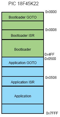
A key consideration for bootloaders is deciding when to bootload. The bootloader program starts when the chip starts. If there is no application program in memory then it goes into bootload mode. That is the easy case. For reloading, a button could be used, for example hold that button down, power up and the bootloader sees the button down and starts the loading process. The application itself could trigger a bootload by writing a value to EEPROM and then resetting, the bootloader would see the special value and could force a bootload.
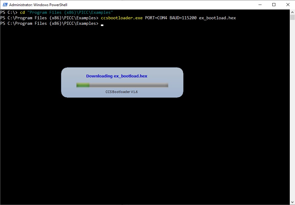
Finally CCS provides a PC program, CCS Bootloader, that can be used to transfer firmware (a .hex file) from a PC to a device that is running a CCS C Compiler bootloader. The CCS Bootloader program is a command line utility that may be distributed as part of the user's end product.
It should be noted that the CCS IDE new project Wizard has an option to create a bootloader for you.
CCS has done bootloaders that work over USB, I2C, CAN, SD cards, USB Flash sticks, TCP/IP and HTTP. Contact us if you need help with your bootloader.
Like us on Facebook. Follow us on Twitter.
About CCS:
CCS is a leading worldwide supplier of embedded software development tools that enable companies to develop premium products based on Microchip PIC ® MCU and dsPIC ® DSC devices. Complete proven tool chains from CCS include a code optimizing C compiler, application specific hardware platforms and software development kits. CCS' products accelerate development of energy saving industrial automation, wireless and wired communication, automotive, medical device and consumer product applications. Established in 1992, CCS is a Microchip Premier 3rd Party Partner. For more information, please visit https://www.ccsinfo.com.
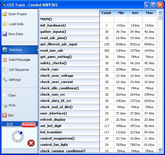
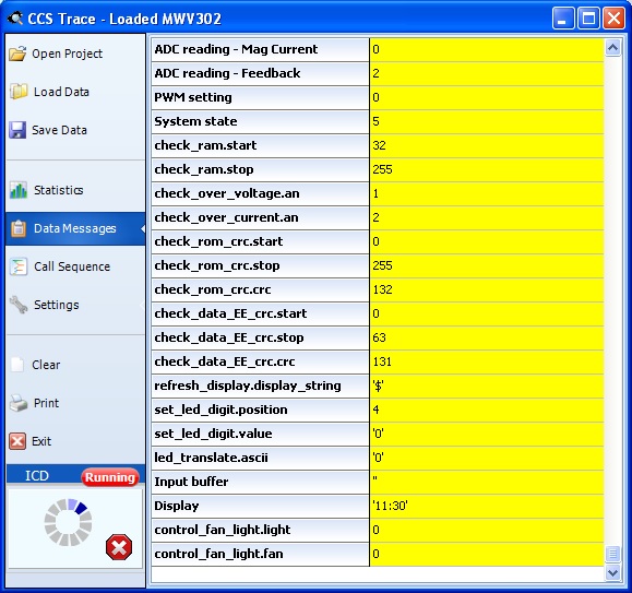
PIC ® MCU, MPLAB ® IDE, MPLAB ® ICD2, MPLAB ® ICD3 and dsPIC ® are registered trademarks of Microchip Technology Inc. in the U.S. and other countries. | November 13, 2020 Expand to read article below The CCS C Compilers have a unique feature called Data Streaming, where an ICD unit is used as a TTL to USB translator. This can do printf()'s and getc()'s through the programming pins to the PC. Many of our users have been using data streaming not only for debugging, but for diagnostics, factory test and calibration.
Using this same interface, the compilers have the ability to inject code to send data out this port at specific points in the code. This information can include a timestamp, as well as, text data. This forms the infrastructure of the code profiling feature in the IDE.
For example, in the code one needs to only add these lines:
#use profile( ICD)
#profile functions
and the compiler inserts a code to transmit a tag at the start and end of every function in the program. When the profile tool is then run in the IDE, the following occurs:
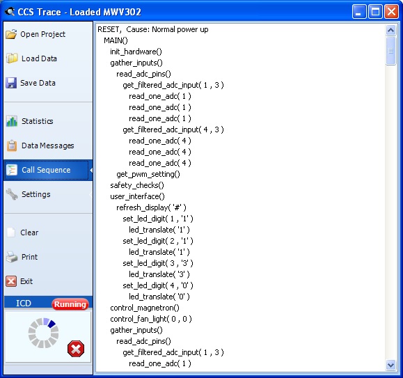
The function tags inserted can optionally include the actual parameters and in the software to get a sequence of events as shown here:
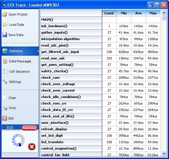
The compiler also allows user defined areas of code to be timed. The user can specify a start and stop event and give the timer a name. A profileout() call is used with text starts with START, followed by something and then another profileout with STOP, and the same something will cause a timer to be created in the software. For example:
profileout("Start interpolation algorithm");
y2=((x2-x1)*(y3-y1))/(x3-x1)+y1;
profileout("Stop interpolation algorithm");
Notice the 4th line down:
profileout() can also be used to output the values of variables real-time. For example:
profileout("value=", value); // Sends a variable and a title for the variable
profileout( value ); // Sends a variable and the title is the variable name
An example screen showing the profileout() data:
The compiler can also be set up to insert tags at every branch in the program or between specific points to help with full path testing. If users own an IDE compiler and a CCS ICD-U64 or ICD-U80, this is a feature that can help users a great deal and is very easy to get going.
Like us on Facebook. Follow us on Twitter.
About CCS:
CCS is a leading worldwide supplier of embedded software development tools that enable companies to develop premium products based on Microchip PIC ® MCU and dsPIC ® DSC devices. Complete proven tool chains from CCS include a code optimizing C compiler, application specific hardware platforms and software development kits. CCS' products accelerate development of energy saving industrial automation, wireless and wired communication, automotive, medical device and consumer product applications. Established in 1992, CCS is a Microchip Premier 3rd Party Partner. For more information, please visit https://www.ccsinfo.com.
PIC ® MCU, MPLAB ® IDE, MPLAB ® ICD2, MPLAB ® ICD3 and dsPIC ® are registered trademarks of Microchip Technology Inc. in the U.S. and other countries. | October 26, 2020 Expand to read article below The CCS C Compiler from the beginning has made it easy to communicate over an RS232 like port. Many of our users have used this extensively, not only for communicating with serial devices but also for diagnostics and debugging. Now, PC's and many other devices have replaced their RS232 ports with USB ports. The USB hardware and software is much more complex than RS232. This has discouraged many from migrating over or they have used a crutch like an external chip to do the USB magic (like FTDI). This article shows how to easily add a USB port to your PIC® MCU application.
HARDWARE
Microchip has a number of chips with built in USB. For example, the PIC16F1459 ($1.38/100) or PIC18F14K50 ($1.79/100). Here is an example schematic: (note: pin numbers apply to PDIP, SOIC, and SSOP packages)
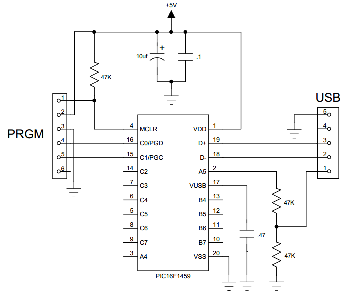
Shown here is a USBmicro style connector. The more common type B connector is the same pinout except there is no pin 5 and 4 is the ground. The D+ and D- pins are for the data and sometimes there will be a 27 ohm series resistor and/or zener protection diodes on those pins. When using a peripheral device, pin 1 will supply 5 volts (up to a half amp). The board can be powered from that 5 volts; however, in this schematic it is to simply detect if the USB cable is plugged in. Although users can do that from the data lines, it is easier to detect the 5 volts like this. Sometimes users will put series coils on the 5 volts and ground to reduce noise.
The Vusb on this chip simply needs a cap for an internal voltage regulator. Some chips have a dedicated Vbus pin for the 5 volts detect. Careful with the pin names, as they are not consistent between chips.
HOST SOFTWARE
The USB bus has a number of protocols that can be used, each with many options and configurations. HID (human Input device) is used for keyboards and mice and is easy to use on any OS because the drivers are built in. There is a data limit however, (like 8 bytes per ms) that makes it impractical for many applications. CDC is a protocol designed to emulate an RS232 port. The Windows drivers will create a virtual COM port for a CDC USB device so the PC application can use COM1... just like an RS232 port.
When a Windows 10 sees a CDC device, it automatically installs a driver for it. For older versions of Windows, users need a short .inf file to describe their device and include the device VID (vendor ID) and PID (product ID). Examples .inf files are in the CCS C Compiler examples directory. Every USB device is supposed to have a unique VID/PID and serial number. If users have two of the same devices plugged in, the VID/PID will match but they are differentiated by serial number. To get a VID users need to register with the USB standards organization.
USB is point to point and one point is a host and the other a device. Hub's can also be involved but that is beyond our concern for this article. The host initiates all activity. For example, a PC is a host and it will poll every device about once a millisecond and transfer any data needing transferring. When the device is first plugged into a port, there is a handshaking that takes place that involves the device identifying itself along with the protocol it will use and various parameters. For example, how much current it expects to draw off the bus. This handshake is called enumeration. In Windows users know it happened by the beep.
Some PIC24 parts have USB hardware that can also be a host. For example, this might be used to read a USB flash drive.
PIC® MCU SOFTWARE
The CCS C Compiler has several example programs for CDC as well as the required drivers. The following are the key declarations you need for a USB CDC program:
#include <16F1459.h>
#use delay(internal=48MHz,USB_FULL,ACT=USB)
#define USB_CON_SENSE_PIN PIN_A5 // Connected to USB +5V
#define USB_STRINGS_OVERWRITTEN
#define USB_CONFIG_VID 0x2405 // CCS VID
#define USB_CONFIG_PID 0x8001
#define USB_DESC_STRING_TYPE 3
#define USB_STRING(x) (sizeof(_UNICODE(x))+2), \
USB_DESC_STRING_TYPE,_UNICODE(x)
#define USB_ENGLISH_STRING 4,USB_DESC_STRING_
TYPE,0x09,0x04
//Microsoft Defined for US-English
Incoming and outgoing data is buffered and transfer is controlled by the host. The program typically only needs to know if enumerated. To manage all this the USB task needs to be periodically called to do housekeeping. The following is an example main program that simply sends an ADC reading to the host every second:
void main(void) {
setup_adc(ADC_CLOCK_INTERNAL);
setup_adc_ports(sAN10); // B4
set_adc_channel(10);
usb_init();
while(TRUE)
{
if(usb_enumerated())
To see the data start up a terminal program on the PC and select the COM port. In the CCS PCW IDE use TOOLS > Serial Port Monitor. The CDC driver has many more options for more complex programs, however the above function calls plus usb_cdc_getc() not shown here will be all most users need.
Summary
That is all there is to it. Find a suitable chip, add a USB connector and slip some of the above into the program. For high speed transfers there is a USB bulk mode, however the driver interface is more complex and there is no standard. Several companies have free generic USB bulk drivers that can be used, however the customer will need to install those on the target PC. The CDC protocol can transfer data at the RS232 equivalent of 250K baud, twice the speed of RS232 and it may be faster than many PIC's can produce the data.
Like us on Facebook. Follow us on Twitter.
About CCS:
CCS is a leading worldwide supplier of embedded software development tools that enable companies to develop premium products based on Microchip PIC ® MCU and dsPIC ® DSC devices. Complete proven tool chains from CCS include a code optimizing C compiler, application specific hardware platforms and software development kits. CCS' products accelerate development of energy saving industrial automation, wireless and wired communication, automotive, medical device and consumer product applications. Established in 1992, CCS is a Microchip Premier 3rd Party Partner. For more information, please visit https://www.ccsinfo.com.
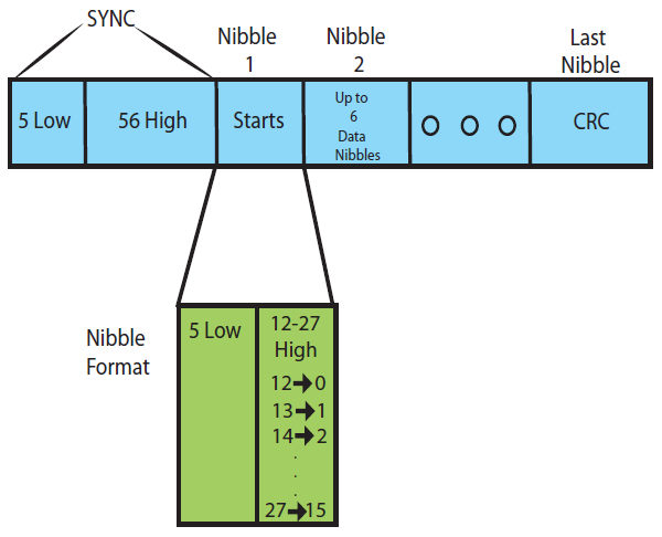
PIC ® MCU, MPLAB ® IDE, MPLAB ® ICD2, MPLAB ® ICD3 and dsPIC ® are registered trademarks of Microchip Technology Inc. in the U.S. and other countries. | October 26, 2020 Expand to read article below The SENT (Single Edge Nibble Transmission) protocol is a relatively new protocol used in the automotive industry for transmitting sensor data to a controller. The SENT protocol is a one-way asynchronous voltage interface which requires three wires, a signal line, a supply voltage line and a ground line. SENT uses pulse width modulation to encode 4 bits (1 nibble) of data per symbol.
The basic unit of time in SENT is a tick, which can be between 3-90us. Each SENT message contains a sync period, made up of 5 low ticks and 56 high ticks, followed by up to 8 nibbles of data. Each data nibble is transmitted with a fixed-width low period of 5 ticks, followed by a variable-length high period from 12 to 27 ticks representing a nibbles value from 0 to 15. The data portion of the SENT message is make up of a status nibble, 1 to 6 nibbles of sensor measurements and a CRC nibble. Additionally, an option pause pulse can be used to compensate for variable message lengths.
Some of Microchip's newer PIC® microcontrollers, the dsPIC33EV256GM106 family for example, comes with a build-in SENT peripheral for transmitting or receiving SENT messages. The CCS C Compiler has build-in functions for setting up and using the SENT peripheral For these devices. The devices that have a SENT peripheral, the following functions will be available in the compiler for setting up and using the SENT peripheral: setup_sent(), sent_putd(), sent_getd() and sent_status().
The setup_sent() function is used to setup the SENT peripheral and has a parameter for setting up as an asynchronous SENT transmitter, synchronous SENT transmitter or a SENT receiver and the number of data nibbles to sent or receive. Other settings include whether to use the pause pulse.
The sent_putd() function is used to load the data nibbles to transmit when the peripheral is setup as a SENT transmitter, and the sent_getd() function is used to retrieve the data nibbles when the peripheral is setup as a SENT receiver. Finally, the sent_status() function is used to get the status of the SENT peripheral, for example what nibble it is currently transmitting or receiving.
The CCS C Compiler also provides two examples ex_sent_transmitter.c and ex_sent_receiver.c showing how use the SENT peripheral and built-in functions. ex_sent_transmitter.c is an example demonstrating how to setup and use the SENT peripheral as an asynchronous SENT transmitter, and ex_sent_receiver.c is an example show how to setup and use the SENT peripheral as a SENT receiver.
Like us on Facebook. Follow us on Twitter.
About CCS:
CCS is a leading worldwide supplier of embedded software development tools that enable companies to develop premium products based on Microchip PIC® MCU and dsPIC® DSC devices. Complete proven tool chains from CCS include a code optimizing C compiler, application specific hardware platforms and software development kits. CCS' products accelerate development of energy saving industrial automation, wireless and wired communication, automotive, medical device and consumer product applications. Established in 1992, CCS is a Microchip Premier 3rd Party Partner. For more information, please visit https://www.ccsinfo.com.
PIC® MCU, MPLAB® IDE, MPLAB® ICD2, MPLAB® ICD3 and dsPIC® are registered trademarks of Microchip Technology Inc. in the U.S. and other countries. | October 26, 2020 Expand to read article below LoRa is low-power wide-area network protocol that can be used to periodically communicate sensor data. LoRa uses a proprietary spread spectrum modulation that is similar to and a derivative of Chip Spread Spectrum (CSS) modulation. This allows for long-range transmission, up to 15 km, with low power consumption. This makes it ideal for battery applications that only need to periodically transmit sensor data.
There are two types of networks that can be built using LoRa modulation. The first is a peer-to-peer or point-to-point network. This is the simplest network that can be created only requiring a minimum of two devices with LoRa radios to develop. In this type of network, each device's radio must set to use the same LoRa settings frequency, coding rate, spreading factor, etc. This type a network is good for small networks with only a few devices that periodically need to transmit data to each other.
The second network type of network described in this article using LoRa modulation is a LoRaWAN network. LoRaWAN is a upper level network protocol, developed by the LoRa Alliance, that uses LoRa modulation for creating a cloud-based network. In LoRaWAN networks end-devices periodically send messages to a gateway, which then forwards to a network server, which forwards it to an application server. Any response is then forwarded back in the reverse order. In order for a device to communicate on a LoRaWAN network it must first join that network, additionally for security purposes the data being sent and received on a LoRaWAN network is encrypted twice. First, the application payload is encrypted with an application key that is only known by the device and application server. Second, the network payload, which includes the application payload, is encrypted with a network key that is only know by the device and the network. This ensures that the data being sent by the end-device to the application is secure.
When developing a LoRaWAN network it requires at least one end-device with a LoRa radio, a gateway, a network server and an application server. However, it is possible to purchase or build a gateway that have the network and application servers built-in to it. Additionally there are several service providers, The Things Network for example, that have public gateways operating in many areas of the world that can be used to receive messages and forward them to your application server. See thethingsnetwork.org for more info about their service. This allows building a LoRaWAN network quickly without investing a lot of time and money in developing and maintaining the network infrastructure. However these services are not required, it is possible to build a private network from the ground up using your own gateways and servers.
Devices that communicate using LoRa modulation requires a LoRa radio, for that purpose Microchip developed the RN2903 module. The RN2903 modules is designed to communicate using LoRa modulation using the US frequency band, additionally the RN2903 module has a built-in stack for connecting to and communicating on a LoRaWAN network.
CCS created a driver for the RN2903 module to assist in development, rn2903.c, for communicating with and controlling the module. The rn2903.c driver is a low level driver that uses serial messages to communicate with and control the RN2903 module. It also has specific functions for controlling RN2903 module's radio, which are used for doing peer-to-peer, point-to-point, communication, and for controlling the RN2903 module's LoRaWAN stack, which is used for connecting to and communicating on a LoRaWAN network. In addition to the rn2903.c driver, CCS also created two additional drivers, lora.c and lorawan.c. The lora.c driver was developed by CCS to use the rn2903.c driver to do peer-to-peer, point-to-point, communication. This is designed so that two or more PIC® MCU devices with RN2903 modules can communicate with each other. The lorawan.c driver was developed by CCS to use the rn2903.c driver to connect a PIC® MCU device with an RN2903 module to a LoRaWAN network. All three of these driver come with the the current version of the CCS C Compiler. CCS will be releasing a LoRa development kit in the near future.
Like us on Facebook. Follow us on Twitter.
About CCS:
CCS is a leading worldwide supplier of embedded software development tools that enable companies to develop premium products based on Microchip PIC® MCU and dsPIC® DSC devices. Complete proven tool chains from CCS include a code optimizing C compiler, application specific hardware platforms and software development kits. CCS' products accelerate development of energy saving industrial automation, wireless and wired communication, automotive, medical device and consumer product applications. Established in 1992, CCS is a Microchip Premier 3rd Party Partner. For more information, please visit https://www.ccsinfo.com.
PIC® MCU, MPLAB® IDE, MPLAB® ICD2, MPLAB® ICD3 and dsPIC® are registered trademarks of Microchip Technology Inc. in the U.S. and other countries. | September 15, 2020 Expand to read article below Many of our loyal compiler customers may not be aware that 10 years ago, CCS bought another company that now operates out of our same location. West Mountain Radio ("WMR") manufactures accessories for the Amateur (HAM) radio and DC power markets. We know many of our customers are Electrical Engineers and most EE's seem to at least be knowledgeable about HAM radio even if they do not indulge themselves. Since the beginning, HAM's have been on the cutting edge of RF technologies, electronic design, computers and software. While the rest of the world is downloading apps, HAMs have been using DSP's to replace most analog components in radios. Software defined radios do tuning, bandwidth control, modulation, demodulation and much more all in software. Digital transmissions are used not only for voice, but modes similar to texting, and e-mail, as well has hybrid communications systems using both RF and the internet. HAMs were experimenting with phone line patches to radios before we had cell phones. HAM radio was truly made for tinkerers.
CCS bought WMR to help smooth out the income stream as the PIC market fluctuates. The company had innovative products and is well respected in the market. What CCS could bring to the table was microcontrollers. Many of the products were crying out for microcontrollers to bring the product line to the next level. This is something our CCS engineers can do in their sleep (or spare time between projects). It also helps to keep our guys on top of the development tool needs for real world applications. As a simple example, WMR has a line of DC power strips. CCS was able to add Ethernet and WiFi to some of these power strips so the voltage and current can be monitored and controlled from any web browser. This is a huge help for unmanned radio stations on a mountain top or for those operating a home station remotely from work.
Many of the traditional WMR products that had clever analog circuits have been upgraded to a small micro. This reduced the number of parts, increased the accuracy and reduced the need for calibration and eliminated drift. On some products, we also put in a small internal USB port so the user could change trip points or just monitor the device status.
We have been a little surprised to find many of our long term customers were also a WMR customer or simply HAM operators. We expect to be showcasing more compiler projects that have HAM radio applications. A new development board is also on the drawing table. Educational package offerings normally reserved for students and schools are being extended to licensed HAM operators.
The HAM radio community is very social. Clubs can be found in any medium to large size city in the US. It is even more popular in other countries. These local clubs will usually sponsor a get together called a HAMFEST. This is an event that has educational seminars, a flea market, license testing and much more. Even if you are not a HAM operator these events are a great place to buy vintage computer equipment, electronics of all types or just have a good high tech conversation with like minded people. WMR sets up a booth at approximately 10 of these shows a year. Sometimes we put out a demo and information on our development kits and compiler. We are considering trying a microcontroller seminar to see what the interest is.
Many of the WMR products have applications well beyond HAM radio. For example, the product line includes sophisticated battery testing, DSP based audio processing for noise reduction, and many DC power related products. The DC power products are special because of the high current they can handle. All the products can deal with at least 40A. A licensed HAM can transmit up to 1500W so high current is important. Beyond HAM radio however, our battery testers can be set up to simulate a specific load pattern to figure out how long a battery will last under a certain scenario. They can also be used just as an electronic load to test a power supply, connectors or just traces on a PCB. If you have some high current designs coming up consider WMR for some of your test equipment.
Let us know if you want to learn more about HAM radio, connect with a local club or just meet us at a show.
To sign up for our WMR newsletter go to:
http://www.westmountainradio.com/content.php?page=newsletters
Like us on Facebook. Follow us on Twitter.
About CCS:
CCS is a leading worldwide supplier of embedded software development tools that enable companies to develop premium products based on Microchip PIC® MCU and dsPIC® DSC devices. Complete proven tool chains from CCS include a code optimizing C compiler, application specific hardware platforms and software development kits. CCS' products accelerate development of energy saving industrial automation, wireless and wired communication, automotive, medical device and consumer product applications. Established in 1992, CCS is a Microchip Premier 3rd Party Partner. For more information, please visit https://www.ccsinfo.com.
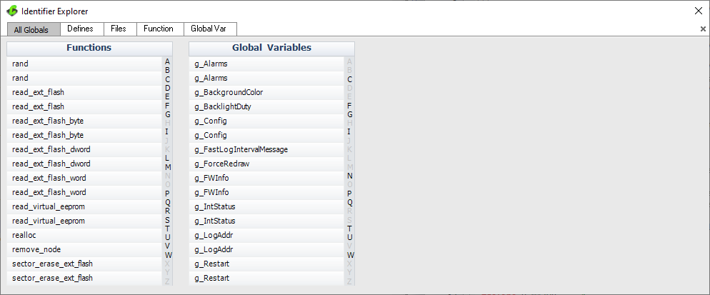
PIC® MCU, MPLAB® IDE, MPLAB® ICD2, MPLAB® ICD3 and dsPIC® are registered trademarks of Microchip Technology Inc. in the U.S. and other countries. | September 15, 2020 Expand to read article below All Globals:
Here we can see all the functions and global variables in the program. Click on any one to get a cross-reference.
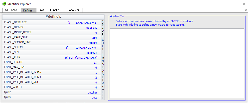
 Defines:
On the left side are all the #defines in the program and the blue shows how they are defined. On the right is a play area where you can type in a macro and it will show you how it is evaluated. For example if you typed FLASH_XFER(4) then it would show you: spi_xfer(LCDFLASH,4). This can be very helpful with complex and/or nested macros.
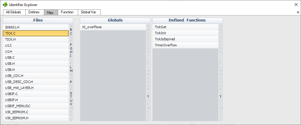
 Files:
Here for each file it will show you the global variables and functions from that file. Clicking on the file moves to that file and clicking on a global or function brings up the cross-reference for that item.
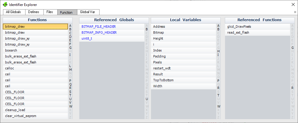
 Function:
This is the cross reference for the functions. Click on a function and you can see the global variables it uses, local variables it defines and functions it calls.
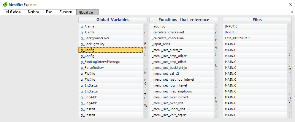
 Global Var:
Click on a global variable name and it shows you each function that uses it and each file that has one of those functions in it.
Like us on Facebook. Follow us on Twitter.
About CCS:
CCS is a leading worldwide supplier of embedded software development tools that enable companies to develop premium products based on Microchip PIC ® MCU and dsPIC ® DSC devices. Complete proven tool chains from CCS include a code optimizing C compiler, application specific hardware platforms and software development kits. CCS' products accelerate development of energy saving industrial automation, wireless and wired communication, automotive, medical device and consumer product applications. Established in 1992, CCS is a Microchip Premier 3rd Party Partner. For more information, please visit https://www.ccsinfo.com.
PIC ® MCU, MPLAB ® IDE, MPLAB ® ICD2, MPLAB ® ICD3 and dsPIC ® are registered trademarks of Microchip Technology Inc. in the U.S. and other countries. |
|