September 22, 2026  Expand to read article below Expand to read article belowThis is a guide to successful In-Circuit Serial Programming (ICSP). To get started, the power connections, the supply voltage, and the bypass capacitors must be suitable for the device that is being programmed. If the ICD will be used for debugging, then the target device must also have an active clock oscillator.
ICSP Cable
Excessive cable length can cause various problems such as: noise pickup, crosstalk, signal reflections, or excessive voltage drop. Be sure to use a cable that is as short as practical for the application. Keep in mind that the circuit board's trace length will add to the overall wiring length. Therefore, place the ICSP connector close to the PIC on the circuit board.
ICSPCLK/PGC (clock) and ICSPDAT/PGD (data):
These are bidirectional data lines. The circuit must be designed in a way that does not significantly alter the voltage levels, rise time, or fall time of the signals. Avoid diodes, pull-up resistors, pull-down resistors, and large value capacitors. Please see Figure 1 for an example of normal PGC (top) and PCD (bottom) signals. It is best to dedicate these pins to ICSP. If the ICD will not be used for debugging, then additional circuitry can be connected to these pins. This allows the pins to be used for other functions after programming has completed, but the circuitry must present a high impedance during programming. If the additional circuitry does not present a sufficiently high impedance, a resistor can typically be added between the PIC ® MCU pin and the additional circuitry. This can minimize the undesired loading affects of the additional circuitry and allow successful programming. If a resistor is not suitable, then the circuit can include a switch or a jumper instead. After programming has been completed, the switch or jumper would be used to connect the additional circuitry to the PIC ® MCU.
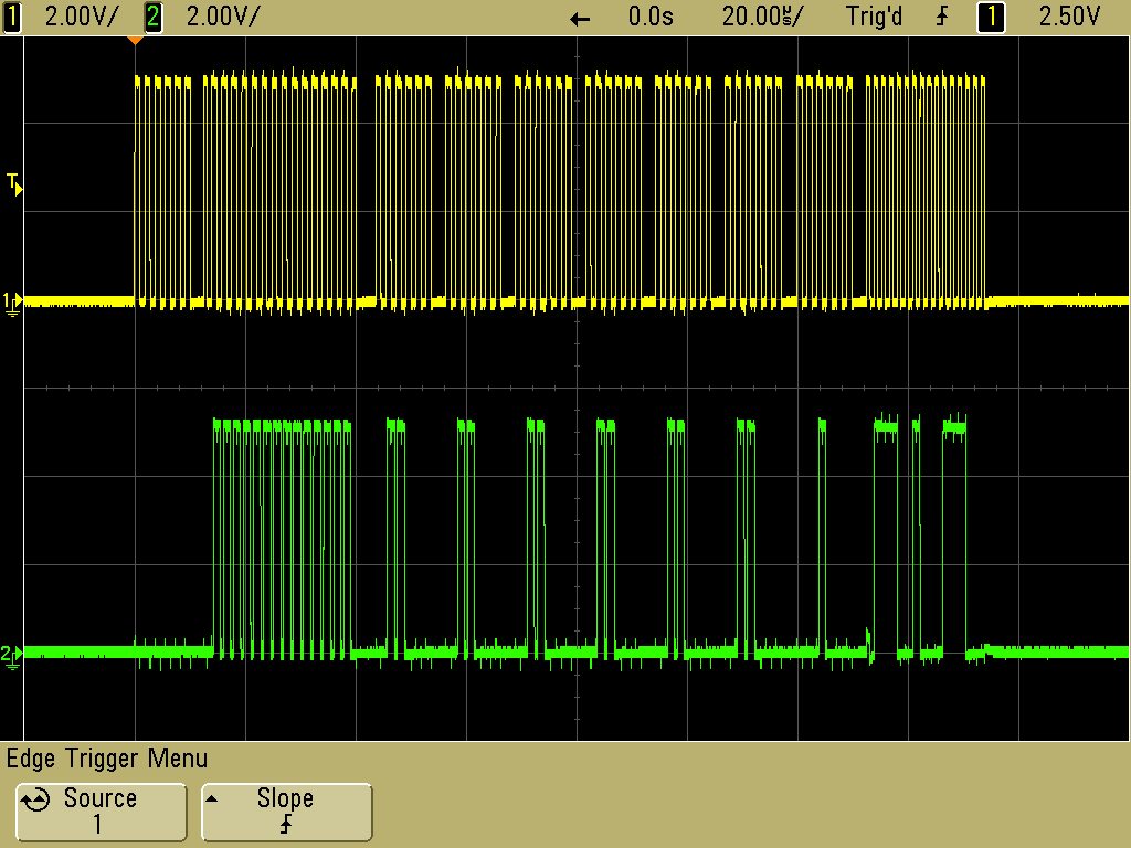
Figure 1
In general, we do not advise the use of capacitors on PGC or PGD. However, there is an exception for electrically-noisy environments and/or unusually long ICSP cables. In these situations, it can be helpful to include a 68pF capacitor from PGC to ground and a second 68pF capacitor from PGD to ground. This can help with noise suppression.
To help with design flexibility, some PIC ® MCU devices have more than one pair of PGC/PGD pins. Any pair can be used for programming. There are configuration bits to select the pair that is used for debugging.
/MCLR (Master Clear, active lo)
The circuit must be designed in a way that does not significantly alter the voltage levels, rise time, or fall time of the signal during programming or debugging. In many situations, only a pull-up resistor is required here. CCS recommends a 47K pull-up resistor. Please see Figure 2 for an example of a normal /MCLR signal.
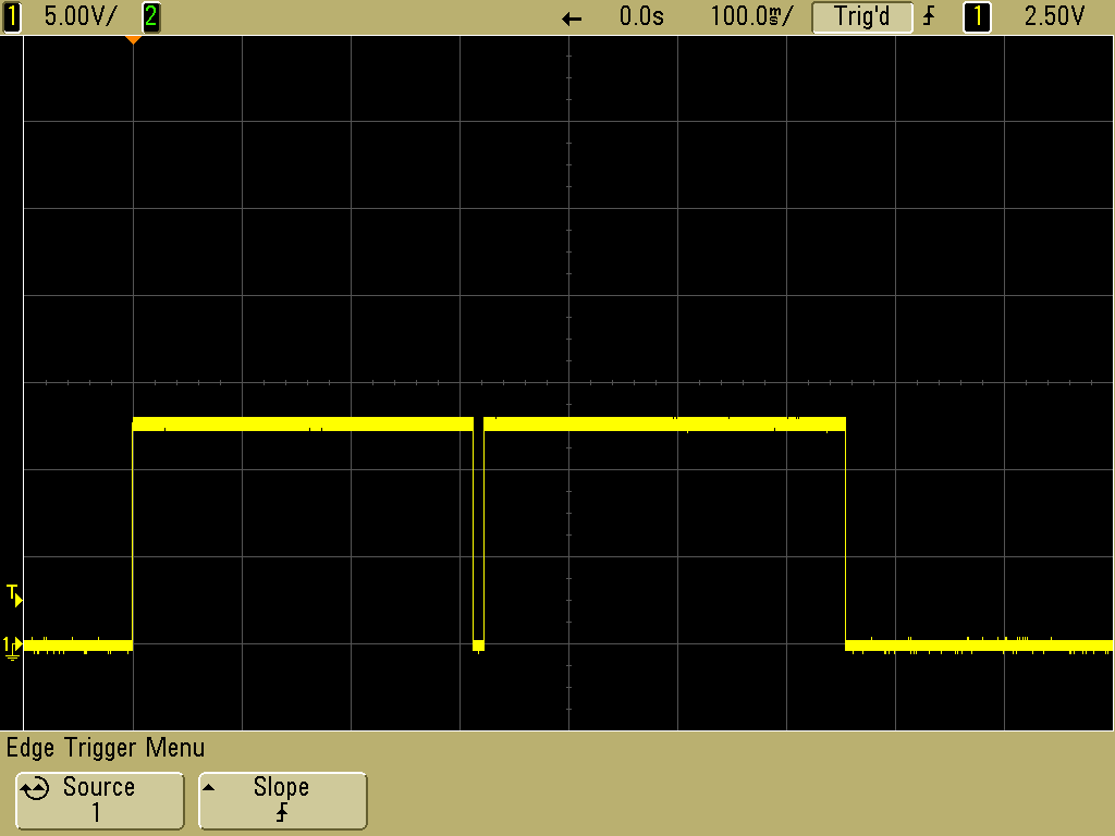
Figure 2
Many PIC ® MCU devices include a Power-up Timer (PUT) which can be enabled in the device's configuration bits. For most applications, the PUT eliminates the need for a capacitor on the /MCLR pin. If a capacitor is connected between the pull-up resistor and ground, include a resistor or a diode between the capacitor and the /MCLR pin on the PIC ® MCU. This will minimize the affect of the capacitor during programming / debugging. Microchip literature recommends a Schottky diode or a 470 Ohm resistor. If a Schottky diode is used, the cathode would connect to the /MCLR pin on the PIC ® MCU. The /MCLR pin on the PIC ® MCU will always connect directly to the /MCLR pin on the circuit board's ICSP connector when an ICD-U80 (or other CCS programmer) is used.
For some PIC ® MCU devices, up to +13V is supplied to the /MCLR pin during programming. The circuit must be designed in a way that is tolerant of that voltage. The 47K pull-up resistor is a good way to deal with that voltage.
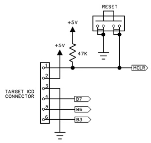
Figure 3 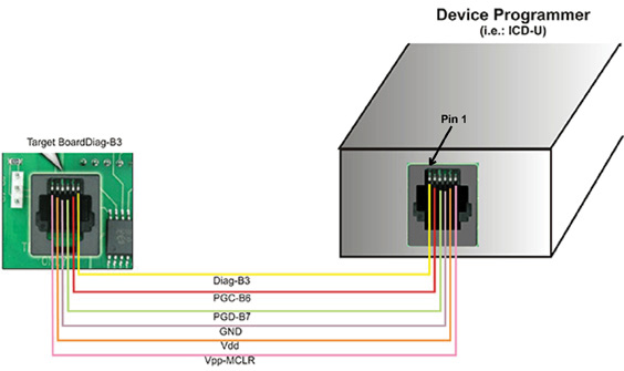
Figure 4 Help with Diag-B3, Pin 6 on Target Board ICSP Connector
During debugging, Pin 6 may be used to interact with a monitor inside of the debug window. This allows for printf()'s and getc()'s in the code to show up in the debugger. Any PIC ® MCU I/O pin may be selected and the use of pin 6 is optional. Note that the CCS ICD units can also be used outside of a debugger to have this same capability with the PGC/PGD pins. In that configuration, the ICD acts like a TTL-to-serial converter.
Use of the Troubleshooting Aids on the CCSLOAD Diagnostics Tab
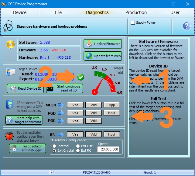
When the Diagnostics Tab is selected, the software will report the measured supply voltage in the target circuit and it will report the device ID that is read from the target device. Note: 12-bit PIC ® MCU devices do not report a device ID.
1. Check the voltage on the screen to be sure it matches the target chip. If not, check the cable connections for power and verify the power source is set right.
2. Check to see if there is green checkmark indicating the device ID is right. If so, the hardware connections are likely good. To verify, click on "Start continuous read of ID" and watch the lower right to see if there are intermitent problems that may be caused by noise. If there seems to be a problem, use a scope to view the signals real time.
3. With no green checkmark, you should check the connections for PGC, PGD and MCLR using the gray buttons in the lower part of the window. Use a DVM connected directly to the chip to verify that the voltage at each pin can be changed by the software.
For additional help, please contact CCS Technical Support:
https://www.ccsinfo.com/contactEmail.php?dept=ts
References:
Microchip PICkit 2 User Guide
Microchip MPLAB PICkit 5 User Guide
Microchip In-Circuit Serial Programming (ICSP) Guide
CCS FAQ, How do I connect the ICD-S/U to my PIC ® MCU hardware?:
https://www.ccsinfo.com/faq.php?page=connect_icd
Like us on Facebook. Follow us on X (Twitter).
About CCS:
CCS is a leading worldwide supplier of embedded software development tools that enable companies to develop premium products based on Microchip PIC ® MCU and dsPIC ® DSC devices. Complete proven tool chains from CCS include a code optimizing C compiler, application specific hardware platforms and software development kits. CCS' products accelerate development of energy saving industrial automation, wireless and wired communication, automotive, medical device and consumer product applications. Established in 1992, CCS is a Microchip Premier 3rd Party Partner. For more information, please visit https://www.ccsinfo.com.
PIC ® MCU, MPLAB ® IDE, MPLAB ® ICD2, MPLAB ® ICD3 and dsPIC ® are registered trademarks of Microchip Technology Inc. in the U.S. and other countries. | September 22, 2026 Expand to read article below Thanks to a gracious CCS customer, a VS Code extension is now publicly available for the CCS C Command-line Compilers. It is an alpha-stage, non-official and non-affiliated VS Code extension, so use at your own risk. The extension is called PICC CCS Support and can be found in the Visual Studio Code Marketplace. Learn more or install from this page: https://marketplace.visualstudio.com/items?itemName=pgvt.picc-ccs-support
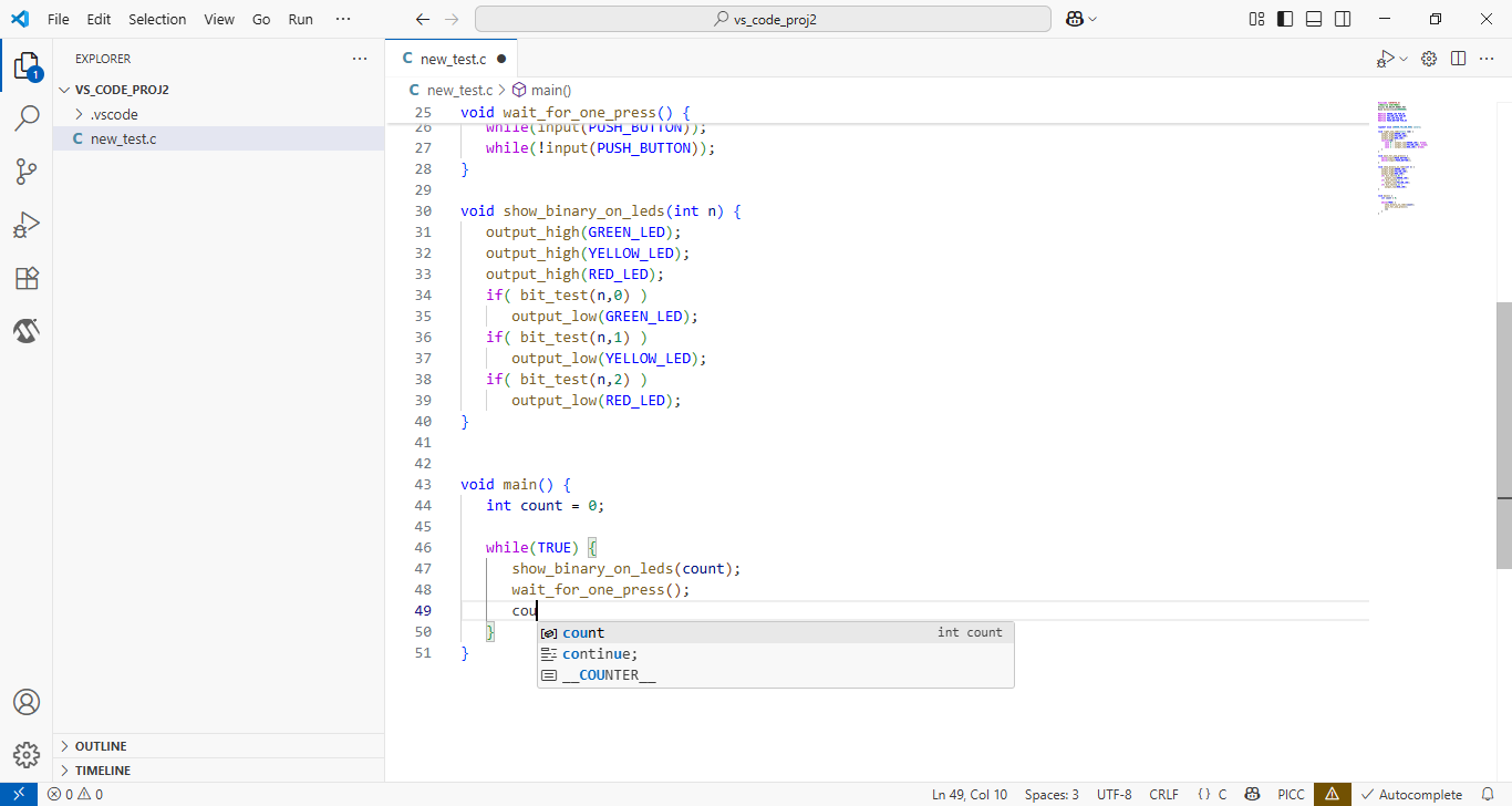
The CCS IDE comes with many more features including a debugger, but there is one notable feature that the VS Code extension offers - automatic intellisense. The CCS IDE comes with a code completion feature that is turned on by default. It automatically brings up code completion suggestions for things like elements of a structure after typing the decimal. However, for things like variables and functions, you must start typing the name and then use Ctrl + Space to bring up suggestions. The VS Code extension automatically brings up code completion suggestions for everything as you are typing.
If you are using Visual Studio Code, you may also want to install the MPLAB AI Coding Assistant extension from Microchip. This extension can give detailed answers to questions about a specific Microchip PIC® MCU device that you are programming.
If you are interested in having AI assist you with reading and writing CCS C code, there are at least a few AI models that partially understand code written for the CCS C compiler. These include ChatGPT, Copilot, and Claude.
Like us on Facebook. Follow us on X (Twitter).
About CCS:
CCS is a leading worldwide supplier of embedded software development tools that enable companies to develop premium products based on Microchip PIC® MCU and dsPIC® DSC devices. Complete proven tool chains from CCS include a code optimizing C compiler, application specific hardware platforms and software development kits. CCS' products accelerate development of energy saving industrial automation, wireless and wired communication, automotive, medical device and consumer product applications. Established in 1992, CCS is a Microchip Premier 3rd Party Partner. For more information, please visit https://www.ccsinfo.com.
PIC® MCU, MPLAB® IDE, MPLAB® ICD2, MPLAB® ICD3 and dsPIC® are registered trademarks of Microchip Technology Inc. in the U.S. and other countries. | September 22, 2026 Expand to read article below CCS recently came out with new programmer/debugger drivers. These drivers allow all CCS programmers/debuggers to work on computers running Windows on Arm® processors.
CCS device programmers only work with 32 or 64-bit Windows on Intel®, AMD or Arm® processors, or with Linux on Intel® or AMD processors.
Installation directions for the new drivers can be found on the following FAQ page: https://www.ccsinfo.com/faq.php?page=arm_drivers
Like us on Facebook. Follow us on X (Twitter).
About CCS:
CCS is a leading worldwide supplier of embedded software development tools that enable companies to develop premium products based on Microchip PIC® MCU and dsPIC® DSC devices. Complete proven tool chains from CCS include a code optimizing C compiler, application specific hardware platforms and software development kits. CCS' products accelerate development of energy saving industrial automation, wireless and wired communication, automotive, medical device and consumer product applications. Established in 1992, CCS is a Microchip Premier 3rd Party Partner. For more information, please visit https://www.ccsinfo.com.
PIC® MCU, MPLAB® IDE, MPLAB® ICD2, MPLAB® ICD3 and dsPIC® are registered trademarks of Microchip Technology Inc. in the U.S. and other countries. | September 22, 2026 Expand to read article below SPI, or Serial Peripheral Interface, is a synchronous serial communication protocol used to enable data exchange between a master device (like a microcontroller) and one or more peripheral (slave) devices. Microchip's PIC® microcontrollers often come with built-in SPI modules (sometimes labeled as MSSP - Master Synchronous Serial Port). These can be configured either as master or slave via software.
SPI operates using four main lines: SCK (Serial Clock), MOSI (Master Out Slave In), MISO (Master In Slave Out), and SS or CS (Slave Select or Chip Select). The master generates the clock signal on the SCK line and initiates communication by selecting a specific slave using the CS line. Data is then transmitted bit by bit, with the master sending data on the MOSI line and receiving data on the MISO line simultaneously, allowing for full-duplex communication. This simple and fast protocol is commonly used in embedded systems for connecting devices like sensors, memory chips, and displays.
CCS provides a support library for taking advantage of both hardware and software based SPI functionality. Hardware SPI uses the built-in SPI peripheral inside the microcontroller. Software SPI bit-bangs the I/O pins. The setup_spi() library is for hardware SPI, while the #use spi() library can be used for both hardware and software SPI. The following is an example showing how to use #use spi() for software SPI:
#use spi(MASTER, SPI_CLOCK=PIN_C3, SPI_DI=PIN_C4, SPI_DO=PIN_C5, MODE=0, BITS=8, STREAM=SPI_STREAM)
BYTE wData[128];
BYTE rData[128];
// Fill wData with the data to transfer
// Send 128 bytes and save the received data to rData
spi_transfer(SPI_STREAM, wData, rData, 128);
// Send 0xAA and receive a byte at the same time
int8 response = spi_xfer(SPI_STREAM, 0xAA, 8);
In this example, we are setting the master device. After setting all of the proper parameters in #use spi(), either the spi_transfer() function or the spi_xfer() function can be used to both transfer and receive data on the SPI bus. The spi_xfer() function lets you set how many bits of data will be transferred. The spi_transfer() function is designed for sending one or more bytes at a time. It is generally faster for larger data transfers, as it handles multiple bytes in a single call. The following is an example of how to set up #use spi() for hardware SPI:
#use spi(MASTER, SPI1, MODE=0, BITS=8, STREAM=SPI_STREAM, ENABLE=PIN_C0, DO=PIN_C5, DI=PIN_C4)
The setup_spi() library should be used when you want to configure hardware SPI manually and use register-level access. The compiler has functions to directly access the MSSP hardware SPI for users with special needs. The following is an example showing how to use setup_spi():
setup_spi(SPI_MASTER | SPI_CLK_DIV_16 | SPI_L_TO_H | SPI_XMIT_L_TO_H);
spi_write(0xAA);
int data = spi_read();
This example sets the master device and uses the spi_write() function to send the data and the spi_read() function to read the data.
Like us on Facebook. Follow us on X (Twitter).
About CCS:
CCS is a leading worldwide supplier of embedded software development tools that enable companies to develop premium products based on Microchip PIC ® MCU and dsPIC ® DSC devices. Complete proven tool chains from CCS include a code optimizing C compiler, application specific hardware platforms and software development kits. CCS' products accelerate development of energy saving industrial automation, wireless and wired communication, automotive, medical device and consumer product applications. Established in 1992, CCS is a Microchip Premier 3rd Party Partner. For more information, please visit https://www.ccsinfo.com.
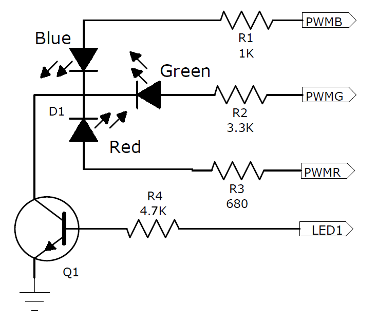
PIC ® MCU, MPLAB ® IDE, MPLAB ® ICD2, MPLAB ® ICD3 and dsPIC ® are registered trademarks of Microchip Technology Inc. in the U.S. and other countries. | September 22, 2026 Expand to read article below RGB LEDs work by combining three different colors of light - red, green, and blue - to create a wide range of colors. An RGB LED has three tiny light-emitting diodes (one for each color) inside a single unit. By adjusting the brightness of each diode, the RGB LED can produce various colors, including white. Below is the schematic for an RGB LED.
With the specific RGB LED that we used, the red, green and blue LED chips are different brightnesses when operated at the same current. To achieve similar brightnesses for the red, green, and blue chips in the LED package, we chose to use three different resistance values for R1, R2, and R3.
The brightness can also be adjusted by feeding a PWM signal to the LED and varying the duty cycle. The signal is always 0 to Vdd but the time the signal is at Vdd will vary depending on the duty. For example, 100% duty is full brightness and 0% is off.
Initialization of the PWMs on a PIC18F55Q43:
//0 Turns LED on (100%), 32000 turn LED off
#define PWM_RGB_DEFAULT_DUTY 0
//Setup RGB PWM pins
set_pwm1_duty(1, PWM_RGB_DEFAULT_DUTY);
set_pwm2_duty(1, PWM_RGB_DEFAULT_DUTY);
set_pwm3_duty(1, PWM_RGB_DEFAULT_DUTY);
//Setup one of the 2 output slices that the Dual 16-bit PWM module has
setup_pwm1_slice(1, PWM_STANDARD);
setup_pwm2_slice(1, PWM_STANDARD);
setup_pwm3_slice(1, PWM_STANDARD);
setup_pwm1(PWM_ENABLED | PWM_CLK_FOSC, PWM_RGB_PERIOD - 1, 1); //1KHz PWM
setup_pwm2(PWM_ENABLED | PWM_CLK_FOSC, PWM_RGB_PERIOD - 1, 1);
setup_pwm3(PWM_ENABLED | PWM_CLK_FOSC, PWM_RGB_PERIOD - 1, 1);
Setting the color and brightness:
duty1 = ((uint32_t)PWM_RGB_PERIOD * g_LEDColor.red) / 255;
duty2 = ((uint32_t)PWM_RGB_PERIOD * g_LEDColor.green) / 255;
duty3 = ((uint32_t)PWM_RGB_PERIOD * g_LEDColor.blue) / 255;
duty1 = (PWM_RGB_PERIOD - (((uint32_t)duty1 * g_LEDBrightness) / 100));
duty2 = (PWM_RGB_PERIOD - (((uint32_t)duty2 * g_LEDBrightness) / 100));
duty3 = (PWM_RGB_PERIOD - (((uint32_t)duty3 * g_LEDBrightness) / 100));
set_pwm1_duty(1, duty1);
set_pwm2_duty(1, duty2);
set_pwm3_duty(1, duty3);
Watch a video of a project containing programmable RGB LEDs at:
https://www.ccsinfo.com/content.php?page=led-board
Like us on Facebook. Follow us on X (Twitter).
About CCS:
CCS is a leading worldwide supplier of embedded software development tools that enable companies to develop premium products based on Microchip PIC ® MCU and dsPIC ® DSC devices. Complete proven tool chains from CCS include a code optimizing C compiler, application specific hardware platforms and software development kits. CCS' products accelerate development of energy saving industrial automation, wireless and wired communication, automotive, medical device and consumer product applications. Established in 1992, CCS is a Microchip Premier 3rd Party Partner. For more information, please visit https://www.ccsinfo.com.
PIC ® MCU, MPLAB ® IDE, MPLAB ® ICD2, MPLAB ® ICD3 and dsPIC ® are registered trademarks of Microchip Technology Inc. in the U.S. and other countries. | June 12, 2023 Expand to read article below In order to evaluate expressions the C compiler uses a complex set of rules to get a result that is consistent and as intuitive as possible. Sometimes the coder needs to add an explicit typecast in order to nudge the compiler to do something specific.
To understand this topic we will start with a simple example that will show a possible problem:
int8 x,y;
int16 z;
x=5;
y=100;
z = x * y;
There are two expression evaluations here. One is the * and the second is the =. The order is *, and then =, and that is controlled by operator precedence, another topic. The two operands for the * are eight bit so the eight bit multiply is used, yielding an eight bit result. In this case the result of the multiply will be 244. Then because the = operator has an 8 bit operand and a 16 bit operand, the 8 bit operand is automatically converted (Integral Promotion because of Usual Arithmetic Conversion) to 16 bit by the compiler. Then the assignment is done.
Probably the coder expected a 500 in z, not 244. To fix the situation we can do a typecast on either 8 bit operand like this:
z = (int16)x * y;
Now when the multiply is done the second eight bit operand is converted to 16 bit to match the other operand and the multiply and result are now 16 bit (500).
Note that this concept is not an invention of the CCS C compiler although people who have never had this trouble with another compiler might think it is. A C compiler for a PC for example where an int is 32 bit by default may never cause a problem because the numbers used are much smaller than the default type. Because the CCS C compiler starts with an eight bit int by default, problems are more common.
Having said that, because the rules are somewhat complex and not always fully understood and sometimes not very specific in the specification, the CCS C compiler has tweaked the rules over the years. Sometimes to match the latest interpretation of the spec or sometimes to match a GNU compiler or the Microchip compiler to help in code portability.
Terminology:
Explicit Conversion, or Explicit Cast, or Explicit Typecast, or Tyepcast:
This is where the coder has a typecast that will force a conversion from one type to another. The syntax is (new type)expression and if the new type is compatible the value will be the same. That is to say this is more than a bit for bit movement, for example a float to an integer will have the same value to the extent possible.
Implicit Conversion, or Automatic Conversion:
This is where the compiler uses a set of rules to be detailed later to perform a conversion.
Type Conversion:
Either an Explicit Conversion or Implicit Conversion.
Integral Promotion:
In this case any type conversion where a smaller integer is converted to a larger one (or superior one). The value does not change when promoted.
Usual Arithmetic Conversions:
These are implicit conversions that are made according to the rules when an operator and operands are involved. One operand is converted based on the type of the other operand BEFORE the operator is invoked.
The Rules:
The way to read this table is for each group start at the top and go down until you find the first rule that applies. Use that result and stop.
Be aware that by default the CCS C compiler for 24 bit parts is signed and the size is 16 bits. For all other compilers the default is unsigned and the size is 8 bits. This can be changed using #type so this needs to be taken into account when considering the rules.
The syntax in this table is not real C, just pseudo-code that a C coder should be able to understand.
The table as follows:
| Integer Constant Types |
|---|
| Leading 0 in constant | Unsigned | | Trailing u in constant | Unsigned | Else if default type is signed || is preceded by a minus | Signed | Else if default type is unsigned | Unsigned | | Find the smallest of these types the constant will fit into | int8, int16, int32, int48, int64 | | Integral promotion anytime X is used in an expression (int is the default type) |
|---|
| issigned (X) && bitsin(X)<bitsin(int) && (X>max(signed(X)) | X=>unsigned int | | bitsin(X)<bitsin(int) | X+>int | | Any type conversion from signed to unsigned |
|---|
| bitsin(signed(X)) <=bitsin(unsigned(X)) | X+>unsigned(X) sign extend | Else | X+>unsigned(X) truncate | | Usual Arithmetic Conversions for Binary operations |
|---|
| isfloat(X) && !isfloat(Y) | Y=>typeof(X) | | isfloat(X) && bitsin(X)>bitsin(Y) | Y=>typeof(X) | | Only if both operands are integer: | | bitsin(X)>bitsin(Y) && (X & Y are both signed or unsigned) | Y=>typeof(X) | | bitsin(X)>bitsin(Y) && unsigned(X) && signed(Y) | Y=>typeof(X) | | bitsin(X)>bitsin(Y) && signed(X) && unsigned(Y) | Y=>typeof(X) | | bitsin(X) = bitsin(Y) && unsigned(X) && signed(Y) | Y=>unsigned(Y)
X=>typeof(Y) |
| June 12, 2023 Expand to read article below The Editor in the V5 IDE has a column editing feature. This is useful if there are several lines that start or contain the same block of text but need to be replaced or edited. To use this feature, press the CTRL key on the keyboard while using the left mouse button on the mouse to select a block of text. Pressing DEL will delete that block of text, or typing will replace the text within the block with new text you type on each line.
This can also be used to simply insert the same text at a given spot on a group of lines. To do that select a thin column where you want the text inserted.
There are situations wherein there is a need to make repetitive but identical changes to each line, or copy a block of text and then add the same text or spacing to each line when editing source code. Column editing allows a way to enter or delete text on multiple rows at once.
Access this feature by pressing the CTRL key while making a selection with the left mouse button. This enables selecting a rectangular region to be able to type to replace its contents, paste over it, or delete it.
The following are some examples.
1. Editing identical variable types

In the above illustration, column select the "int" type, and then simply type "unsigned int", to all 3 lines at once.
2. Working with Enums
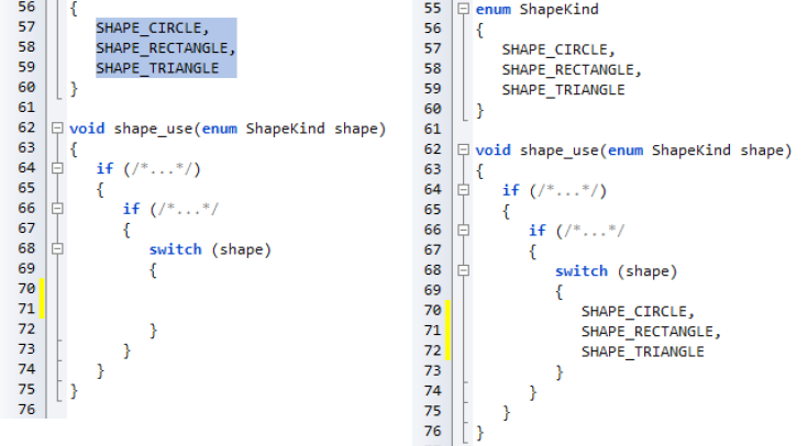
Above shows a selected rectangle consisting of all of the enum variants to avoid copying the spacing. Pasting it into the switch statement maintains its tabbing. Next insert "case" into each line by simply column select the space before "SHAPE" and type "case". | June 12, 2023 Expand to read article below One of the most difficult things to deal with is upgrading a products firmware to fix a bug for products that are already in the field. It can be expensive and time consuming to do a recall of the products or send technicians to update the firmware. One option is to add a bootloader to the product. By using a bootloader it is possible to update a products firmware automatically or by the end user. One of the easiest types of bootloaders to implement is a serial bootloader.
A serial bootloader uses a serial connection, RS232 for example, to transfer the new firmware from a PC to the product, which is then programmed onto the product by a small program that runs on the device. To aid in quickly developing a serial bootloader, the CCS C Compiler has bootloader code that can be included in your project, as well has a PC program that can be used to transfer the firmware to product.
The CCS C Compiler provides the following bootloader examples, ex_bootloader.c and ex_pcd_bootloader.c. The first is an example of a serial bootloader for PIC16 and PIC18 devices, PCM and PCH compilers, and the second is an example of a serial bootloader for PIC24, dsPIC30 and dsPIC33 devices, PCD compiler. Both are an example of a standalone bootloader. Standalone bootloaders are small programs that run on the device that are responsible for both receiving the firmware and for programming it onto the device. In general, standalone bootloaders do not require the application for them to work. The size of a serial bootloader program depends on the device they are being used on, for example the CCS serial bootloader for PIC18 devices use 1280 instructions or 2560 bytes of ROM and always remains at the same location in ROM. Some PIC® MCUs allow you to specially code protect the bootloader area in ROM. Additionally the CCS C Compiler provides the following bootloader applications, ex_bootload.c and ex_pcd_bootload.c. Both are examples of applications that can be bootloaded onto a device using the ex_bootloader.c and ex_pcd_bootloader.c bootloaders. The key difference between a standard application and one that can be bootloaded is that the bootloadable application reserves an area of ROM for the bootloader. Frequently that area includes the reset and interrupt vectors so the application will use an alternate area that the bootloader can link to. In general #including the same bootloader.h file that the bootloader uses is all that needs to be done to build an application that is compatible with the bootloader.
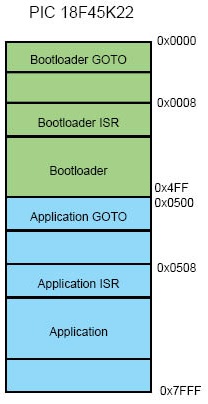
A key consideration for bootloaders is deciding when to bootload. The bootloader program starts when the chip starts. If there is no application program in memory then it goes into bootload mode. That is the easy case. For reloading, a button could be used, for example hold that button down, power up and the bootloader sees the button down and starts the loading process. The application itself could trigger a bootload by writing a value to EEPROM and then resetting, the bootloader would see the special value and could force a bootload.
Finally CCS provides a PC program, CCS Bootloader, that can be used to transfer firmware (a .hex file) from a PC to a device that is running a CCS C Compiler bootloader. The CCS Bootloader program is a command line utility that may be distributed as part of the user's end product. | June 12, 2023 Expand to read article below CAN bus is a message-based protocol allowing individual systems, devices, and controllers within a network to communicate. In general, a bus is a multi-node communication system that transfers data between components. A Controller Area Network allows for robust, low-latency, data transfer between sensors and compute units in a system. Without CAN Bus, wiring harnesses could contain miles of wire, with bundles of wires required to carry various signals to and from interconnected systems. In contrast, CAN bus utilizes a high-speed (25kbps - 1Mbps) twisted pair wiring system, greatly reducing the amount of wire necessary to allow system components to communicate.
The CAN protocol is a serial communication protocol that is used in the automotive industry for communicating between devices inside of a vehicle, the engine control unit and dashboard for example. Data is sent in frames and is done in such a way that if more than one device transmits at the same time the highest priority device is able to continue while the other devices back off. There are two CAN standards that are in use today, CAN 2.0 and CAN FD. CAN 2.0 is the older of the two protocols and has two parts; part A is for the standard format with an 11-bit identifier, commonly called CAN 2.0A, and part B if for the extended format with a 29-bit identifier, commonly called CAN 2.0B. Both parts can transmit data with bit rates up to 1MBit/s with up to 8 data bytes. CAN FD is a newer protocol that has flexible data-rate, an option for switching to a faster data rate, up to 5 Mbits/s, after the arbitration bits, which is limited to 1Mbits/s for compatibility with CAN 2.0, and it increases the max number of data bytes that can be transmitted in a frame to 64. CAN FD is compatible with existing CAN 2.0 networks so new CAN FD devices can coexist on the same network with existing CAN 2.0 devices.
There are several PIC® microcontrollers that have a built-in CAN 2.0 or CAN FD modules. For these devices, the CCS C Compiler comes with drivers for communicating with these protocols. There are separate drivers depending on the device being used. Additionally, the CCS C Compiler comes with several external CAN controllers. The following are a list of can drivers that are currently available in the CCS C Compiler:
- can-pic18f_ecan.c - PIC18 CAN 2.0
- can-pic24_dsPIC33.c - PIC24 and dsPIC33 CAN 2.0
- can-dspic30f.c - dsPIC30 CAN 2.0
- can-mcp2515.c - External MCP2515 controller CAN 2.0
- can-dspic33_fd.c - dsPIC33 CAN FD
- can-mcp2517.c - External MCP2517 controller CAN FD
J1939 is an upper level protocol that specifies how to send messages in a vehicle using the CAN 2.0 and CAN FD protocols. J1939 is maintained by SAE and the full J1939 specifications can be obtained from them. The J1939 is broken into several layers including, but not limited to, the Data Link Layer, Network Layer and Application Layer. These layers contain information about how to communicate on the network, how to claim an address, the format of messages, how often a message can be transmitted, etc. The CCS C Compiler comes with a J1939.c driver which is a library for the Data Link Layer running on a CAN 2.0 protocol network. The library has functions for claiming an address, responding to address claim messages, transmitting J1939 messages and receive J1939 messages.
Additionally, CCS also has several CAN development kits that can be used to aid in developing CAN Bus and J1939 projects. Each development kit has four nodes on it that can communicate with each other, as well as headers allowing the kit to be connected to an external Bus.
The first development kit CCS has is the CAN Bus development kit which has a PIC18F45K80 on the primary node and a PIC16F1938 on the secondary node. The primary node the PIC ® MCU uses its built-in CAN peripheral for communicating on the Bus. The secondary node the PIC ® MCU uses an external MCP2515 CAN controller for communicating on the Bus.
The second development kit CCS has is the CAN Bus 24 development kit which has a PIC24HJ256GP610 on the primary node and a dsPIC30F4012 on the secondary node. Like the previous kit, the primary node the PIC ® MCU uses its built-in CAN peripheral for communicating on the Bus and the secondary node PIC uses an external MCP2515 CAN controller for communicating on the Bus.
The third development kit CCS has is CAN Bus FD which features a dsPIC33CH128MP506 on the primary node and a PIC16F18346 on the secondary node. The primary node the PIC ® MCU uses its built-in CAN FD peripheral for communicating on the bus, and the secondary node the PIC ® MCU uses an external MCP2517 CAN FD controller for communicating on the Bus. | February 10, 2023 Expand to read article below The list file is produced to show the assembly code created for the C source code. Each C source line has the corresponding assembly lines under it to show the compiler's work. The following three special cases make the .LST file look strange to the first time viewer. Understanding how the compiler is working in these special cases will make the .LST file appear quite normal and very useful.
1. Stray code near the top of the program is sometimes under what looks like a non-executable source line.
Some of the code generated by the compiler does not correspond to any particular source line. The compiler will put this code either near the top of the program or sometimes under a #USE that caused subroutines to be generated.
2. The addresses are out of order.
The compiler will create the .LST file in the order of the C source code. The linker has re-arranged the code to properly fit the functions into the best code pages and the best half of a code page. The resulting code is not in source order. Whenever the compiler has a discontinuity in the .LST file, it will put a * line in the file. This is most often seen between functions and in places where INLINE functions are called. In the case of an INLINE function, the addresses will continue in order up where the source for the INLINE function is located.
3. The compiler has gone insane and generated the same instruction over and over.
For example:
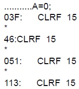
This effect is seen when the function is an INLINE function and is called from more than one place. In the above case, the A=0 line is in an INLINE function called in four places. Each place it is called from gets a new copy of the code. Each instance of the code is shown along with the original source line, and the result may look unusual until the addresses and the * are noticed. |
|