CAN Bus FD Development Kit
| Development Kit Options | |||
| Tools Included | w/Compiler | Hardware Only* | Proto- Board* |
| Sku | S-219 | 53222-1857 | 53222-1856 |
| Compiler Software | |||
| Programmer | |||
| Prototyping board | |||
| Power supply & cables | |||
| Exercise book | |||
| Price | $774 | $199 | $97 |
| *Hardware only and proto-boards are intended for customers already owning a CCS compiler. View Details. Restock date not available; planned for future production. | |||
This kit enables users to begin CAN FD network development with Microchip's PIC® PIC16 and dsPIC® DSC families. The development kit includes the powerful PCWHD Integrated Development Environment with compiler support for Microchip's PIC® PIC10, PIC12, PIC16, PIC18, PIC24 and dsPIC® DSC families and an ICD-U80 in-circuit programmer/debugger that supports C-aware real time debugging. The prototyping board has four nodes. CAN drivers and example code are also included.
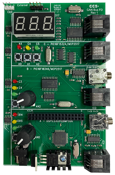
The first node is a dsPIC33CH128MP506 which includes an integrated CAN FD peripheral. This node is connected to three LEDs, a potentiometer, one pushbutton, a RS232 port and 30 I/O pins.
The second node is a PIC16F18346 which includes a MCP2517FD to connect to the CAN FD bus. This node is connected to a potentiometer, three LEDs, one pushbutton, and a RS232 port.
The third node is a PIC16F15324 which includes a MCP2517FD to connect to the CAN FD bus. This node is connected to three LEDs and three push buttons and is pre-programmed to work with the development kit exercises.
The fourth node is a PIC16F18346 which includes a MCP2516FD to connect to the CAN FD bus. This node is connected to three 7-Segment LEDs and is pre-programmed to work with the development kit exercises.
CAN Bus FD Prototyping Board (Size: 5.25" x 3.31") includes:
- dsPIC33CH128MP506
- Two PIC16F18346
- PIC16F15324
- 30 I/O (11 Can Be Analog)
- Three MCP2517FD external CAN FD controllers
- Two Potentiometers
- Nine LEDs
- Three 7-Segment LEDs
- Two RS-232 Ports
- RS-232 Level Converter
- Four ICD Jacks
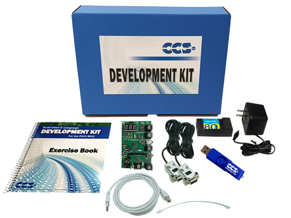
CAN Bus FD Development Kit includes:
- CAN Bus FD Prototyping Board
- In-Circuit Debugger/Programmer
- Exercise Tutorial
- 9V AC Adapter
- Two Serial PC to Prototype Board Cables
- ICD to Prototype Board Cable
- USB PC to ICD Cable
Click here to view the Prototyping Accessories.


