 |
 |
| View previous topic :: View next topic |
| Author |
Message |
viki2000
Joined: 08 May 2013
Posts: 233


|
|
 Posted: Wed Jan 25, 2017 5:51 am Posted: Wed Jan 25, 2017 5:51 am |
 |
|
I do not want to use external crystal. I want to use the internal block oscillator.
I just want to have the fuses in such way set that Configuration Word 2 to be 0x1DFF, similar as I was able to do it with XC8 compiler:
| Code: | #include <xc.h>
#include <pic16f1825.h>
#define _XTAL_FREQ 32000000
// CONFIG1
#pragma config FOSC = INTOSC // Oscillator Selection (INTOSC oscillator: I/O function on CLKIN pin)
#pragma config WDTE = OFF // Watchdog Timer Enable (WDT disabled)
#pragma config PWRTE = OFF // Power-up Timer Enable (PWRT disabled)
#pragma config MCLRE = OFF // MCLR Pin Function Select (MCLR/VPP pin function is digital input)
#pragma config CP = OFF // Flash Program Memory Code Protection (Program memory code protection is disabled)
#pragma config CPD = OFF // Data Memory Code Protection (Data memory code protection is disabled)
#pragma config BOREN = ON // Brown-out Reset Enable (Brown-out Reset enabled)
#pragma config CLKOUTEN = ON // Clock Out Enable (CLKOUT function is enabled on the CLKOUT pin)
#pragma config IESO = OFF // Internal/External Switchover (Internal/External Switchover mode is disabled)
#pragma config FCMEN = OFF // Fail-Safe Clock Monitor Enable (Fail-Safe Clock Monitor is disabled)
// CONFIG2
#pragma config WRT = OFF // Flash Memory Self-Write Protection (Write protection off)
#pragma config PLLEN = ON // PLL Enable (4x PLL enabled)
#pragma config STVREN = OFF // Stack Overflow/Underflow Reset Enable (Stack Overflow or Underflow will not cause a Reset)
#pragma config BORV = LO // Brown-out Reset Voltage Selection (Brown-out Reset Voltage (Vbor), low trip point selected.)
#pragma config LVP = OFF // Low-Voltage Programming Enable (High-voltage on MCLR/VPP must be used for programming)
void main(){
OSCCON = 0xF0;
OSCSTAT = 0x00;
OSCTUNE = 0x00;
LATA = 0b00000000;
TRISA = 0b00101110;
ANSELA = 0x00;
WPUA = 0b00101110;
IOCAP = 0x00;
IOCAN = 0x00;
IOCAF = 0x00;
APFCON0 = 0x00;
APFCON1 = 0x00;
while(1){
LATA0=1;
__delay_us(100);
LATA0=0;
__delay_us(100);
}
} |
|
|
 |
Ttelmah
Joined: 11 Mar 2010
Posts: 20059
|
|
| Posted: Wed Jan 25, 2017 6:37 am |
|
|
You are fundamentally 'missing the point'. The chip _cannot wake up using the PLL with the internal oscillator_. You can set the PLL fuse if you want , but if you do, it won't actually enable the PLL. This is why CCS prevents it.
Microchip lets you program it, but it won't actually work till the oscillator is reprogrammed.
You have to reprogram the oscillator to the 8MHz branch before it can work. If you setup the clock as you are being shown CCS adds the code to do this (and enable the PLL at the same time).
Setting this fuse with the internal oscillator _does not work_.
You can set the fuse explicitly if you must (#fuses address, value), but it won't make any change to the operation of the chip.
Use CCS code, don't try to copy XC8. All the settings you post are basically pointless. |
|
|
viki2000
Joined: 08 May 2013
Posts: 233
|
|
| Posted: Wed Jan 25, 2017 7:44 am |
|
|
Maybe I am missing the point, but my settings are not pointless. They are absolutely necessary to clarify my question.
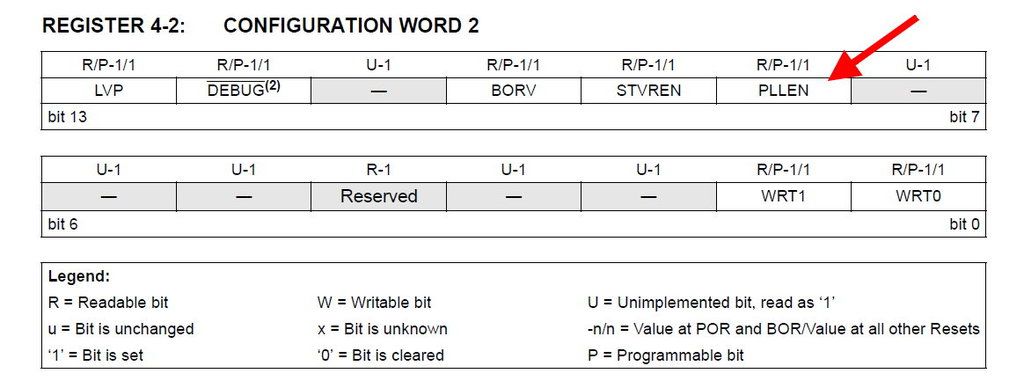
Any by the way, Microchip does mistake too, even in datasheet. It should be written Configuration Word 2 and not 1:
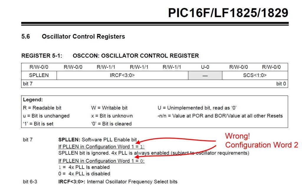
You started to bring some light in here, but I should take it slowly.
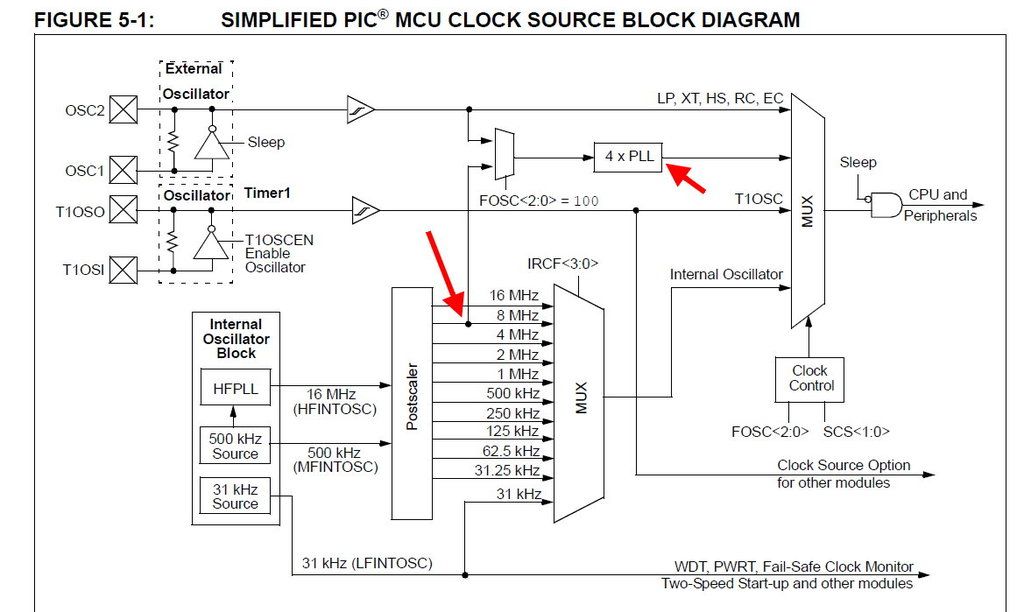
After reset the PIC wakes up with 500KHz default internal frequency, meaning internal oscillator.
If I want 32MHz, then I must set explicitly in software the value of OSCCON register to 8MHz and to enable the PLL.
We have 2bits for PLL in datasheet, one is PLLEN in Configuration Word 2 and then we have SPLLEN in OSCCON register.
The fuses (Configuration Word 1 and 2) are set first, in the beginning and then the OSCCON register comes later in code, either main or a header file.
Is that right?
Now, you tell me that if I choose in CCS the 32MHz, then the compiler automatically makes some settings for me regarding the fuses.
But if I understand right the datasheet, it’s a big book 420 pages : ), it says:
| Quote: | “The SPLLEN bit in the OSCCON register must be
set to enable the 4xPLL, or the PLLEN bit of the
Configuration Word 2 must be programmed to a
‘1’.” |
So is one or another. I have 2 options. And CCS force the situation to always SPLLEN by keeping PLLEN always 0.
I do not want that. I want PLLEN=1 and forget about SPLLEN in OSSCON.
Is nothing wrong in the end, because both options are valid according with the datasheet, but why did the cut access to PLLEN bit in CONFIG2 (PLL bit CCS in #fuses)?
What I expected?
To set the PLL bit in #fuses (equivalent to PLLEN in CONFIG2), ignore the PLL_SW (equivalent to SPPLEN in OSCCON) and later in program obviously to set the internal oscillator to 8MHz.
It was obviously from beginning, also seen in XC8 code, that I set the internal clock to 8MHz in order to get 32MHz.
Then there is that note:
| Quote: | “Note: When using the PLLEN bit of the
Configuration Word 2, the 4xPLL cannot
be disabled by software and the 8 MHz
HFINTOSC option will no longer be
available.” |
Which implies that PLLEN in Configuration Word 2 has priority (if set in fuses) over SPLLEN (equivalent of PLL_SW in CCS) on OSCCON.
Why CCS provides in #fuses the bit PLL when is kept always 0?
It's a question of taste, color? |
|
|
Ttelmah
Joined: 11 Mar 2010
Posts: 20059
|
|
| Posted: Wed Jan 25, 2017 8:53 am |
|
|
The point is that they feel that since if you want the PLL, you have to reprogram the oscillator, it is better to be explicit and perform the switch to 8MHz, and the switch to enable the oscillator as one operation.
There is also a secondary reason, in quite a few of the chips _require_ the software branch to be used when using the internal oscillator - if the hardware selection is made it stops it working...
Having the PLL enabled in hardware won't actually give you a working PLL at boot, so 'better' to leave it off and do the two things with one operation. As you say it is a matter of 'taste', but you obviously thought that MPLAB with this set would give you 32MHz, when it wouldn't, which perhaps makes the point about how misleading this can be.
Also having it set to the software selection also then leaves you free to select 8Mhz, if required.
Jeremiah's clock setting effectively automatically adds (internally) the command 'setup_oscillator(OSC_32MHz); to the code at the start, before anything else is done. So as soon as the chip starts it switches to 32MHz.
CCS does allow you to explicitly set a fuse if required. Look at the last line in the 'purpose' entry in the manual. |
|
|
viki2000
Joined: 08 May 2013
Posts: 233
|
|
| Posted: Wed Jan 25, 2017 9:33 am |
|
|
| Quote: | | but you obviously thought that MPLAB with this set would give you 32MHz, when it wouldn't, which perhaps makes the point about how misleading this can be. |
I am not so sure I understand that.
The XC8 code above provides 32MHz with PLL. I have tested it with a a real PIC. Besides that is proved also by Microchip Code Configurator. |
|
|
temtronic
Joined: 01 Jul 2010
Posts: 9632
Location: Greensville,Ontario
|
|
| Posted: Wed Jan 25, 2017 9:48 am |
|
|
It'd be interesting to compare the XC8 and CCS code(asm NOT C) to see how XC8 handles the setup for 32MHz operation. I get the feeling there's stuff 'hidden' behind the screen....
Jay |
|
|
Ttelmah
Joined: 11 Mar 2010
Posts: 20059
|
|
| Posted: Wed Jan 25, 2017 10:13 am |
|
|
| Yes. The point is that it is not the PLL _fuse_ that is giving the 32Mhz. |
|
|
viki2000
Joined: 08 May 2013
Posts: 233
|
|
| Posted: Thu Jan 26, 2017 2:53 am |
|
|
You mentioned couple of times that I can set the fuses explicitly, but actually “PCM programmer” already tried that on the previous page with a code as below and does not work.
| Code: | #include <16F1825.h>
#fuses 1=0x07A4
#fuses 2=0x1DFF
#use delay(clock=32M)
//======================
void main()
{
while(TRUE);
} |
Let’s assume, as in my case, that I want to use the internal clock at 32MHz.
If I read the datasheet and I go step by step through all the fuses settings, then I do it as in XC8:
1) I set PLLEN in Configuration Word 2 and later in code I ignore the SPLLEN in OSCCON and I set the OSCCON to have 8MHz, which will produce 32MHz due to PLLEN.
2) CCS does it different.
No matter if you use PLL or PLL_SW in #fuses, as long as you set “#use delay(clock=32M)” automatically sets the PLLEN to 0 and uses always PLL_SW by setting SPLLEN 1 in OSCCON.
I am not saying that is necessarily wrong as long as the chip works fine and we get the 32MHz, but it makes you wonder why it is the PLL bit in #fuses still available if it is kept 0 always anyway.
And that makes you wonder further: why not when I say/set PLL, then automatically the clock to be set 32M or the other way around, when I say 32M to have the PLL set, so all automatically to the end. But I am sure it would be a compatibility problem with other chips inside the compiler which must have broader setting options.
Why is like that? Obviously due to some internal CCS compiler settings, either wanting to keep compatibility with other chip families or wanting to reduce the possible user error settings or they cannot do it other way.
For me this is like: “If most of the countries in Europe and the USA drive on the right side, UK drives on left. Why? Because of historical reasons or they have a different mindset.”
If I try to compare this situation with another real world case, comes in my mind next example.
“In a new city, a traffic system is installed with traffic lights and traffic signs. Everything works fine, but a citizen noticed at one intersection a traffic light which is always off, without power, but there are traffic signs. Then he asks why was that traffic light installed anyway if is never alive, even if the traffic flow is all right. And he got next answer: we had a contract with a company which delivered the traffic system with all the traffic lights and traffic signs that you see and they came with a structure and a plan and was installed accordingly, but we have the possibility to enable/disable each traffic light as we want/need to assure a good traffic flow. We keep (momentary) that unused traffic light in position due to possible updates in traffic control software when we may enable it if we consider that will help to a better traffic flow.”
I know it looks as I stumbled on a “bit”, but is good that we had all the above discussions, because is now clear what is happening and we can move one and take it as it is. |
|
|
Ttelmah
Joined: 11 Mar 2010
Posts: 20059
|
|
| Posted: Thu Jan 26, 2017 4:13 am |
|
|
I have explained 'why' before.
The reason CCS deliberately turns this fuse off, is for a couple of other chips. On these if you have the PLL set 'on' in the fuses, you cannot get it to work with the internal clock.
They therefore set the 'mask' for INTRC_IO, to turn this bit off. You can actually override this by changing the mask if you must.
Why are you so 'anti' just leaving it under software control?. Given that you have to write to OSCCON before the PLL can work, which is where the SPLLEN bit sits, you just write 0xF0 to OSCCON. One operation, enables the PLL, and switches to 32Mhz.
CCS inserts:
| Code: |
0003: MOVLW F0
0004: MOVLB 01
0005: MOVWF 19
|
as the first three instructions of the file, which switches to 32MHz. Can't get much simpler...
As an example of one where it doesn't work if you use hardware, look at the data sheet for the 18F6722 (first one I could find):
| Quote: |
2.6.4 PLL IN INTOSC MODES
The 4x Phase Locked Loop (PLL) can be used with the
internal oscillator block to produce faster device clock
speeds than are normally possible with the internal
oscillator sources. When enabled, the PLL produces a
clock speed of 16 MHz or 32 MHz.
Unlike HSPLL mode, the PLL is controlled through
software. The control bit, PLLEN (OSCTUNE<6>), is
used to enable or disable its operation.
The PLL is available when the device is configured to
use the internal oscillator block as its primary clock
source (FOSC3:FOSC0 = 1001 or 1000). Additionally,
the PLL will only function when the selected output frequency
is either 4 MHz or 8 MHz (OSCCON<6:4> = 111
or 110). If both of these conditions are not met, the PLL
is disabled and the PLLEN bit remains clear (writes are
ignored).
|
There are actually quite a few chips where this is the case in the data sheet (and more where it appears as an erratum).... |
|
|
viki2000
Joined: 08 May 2013
Posts: 233
|
|
| Posted: Thu Jan 26, 2017 5:21 am |
|
|
Thank you for explanations. They are really useful.
I am not " 'anti' just leaving it under software control", I mean it works just fine, but it just seemed natural to me to be the other way around as right hand traffic vs. left hand traffic. And this "natural" thing comes from datasheet and XC8 where you can set any bit as you want. I did not expect that CCS does not let you do that. |
|
|
viki2000
Joined: 08 May 2013
Posts: 233
|
|
| Posted: Fri Jan 27, 2017 1:05 am |
|
|
Just to make everyone happy, I asked CCS Technical Support and they provided good explanations:
| Quote: | | “Clock related configuration fuses are set by the #use delay() directive. What it happening is that #use delay() is forcing the PLL_SW fuse. For internal clock setups that requires the PLL what the compiler does is set the PLL_SW configuration fuse and then sets the SPLLEN bit in the OSCCON register to enable the PLL. We do it this way so it's possible to switch the internal clock to non-PLL speeds, specifically 8 MHz. You can always overwrite the fuses #use delay() makes by placing your fuses after the #use delay() line” |
| Code: | #include <16F1825.h>
#use delay(clock=32M)
#fuses 1=0x07A4
#fuses 2=0x1DFF
//======================
void main()
{
while(TRUE);
} |
The things work as we discussed here above and the good news is that we can set the PLL bit if we want with #fuses explicit, as suggested above, if we put them after the “#use delay(clock=32M)” and not before as “PCM Programmer” and I did in previous tests. Everything is fine and clear now. I can see the PLL bit in .LST file.
For these kind of settings is good to discuss and ask, because they are not obviously for everyone when reads manuals or forums, being hidden behind the functionality of the compiler. |
|
|
|
|
You cannot post new topics in this forum
You cannot reply to topics in this forum
You cannot edit your posts in this forum
You cannot delete your posts in this forum
You cannot vote in polls in this forum
|
Powered by phpBB © 2001, 2005 phpBB Group
|

