 |
 |
| View previous topic :: View next topic |
| Author |
Message |
bmete
Joined: 13 Jul 2023
Posts: 37


|
| Communicating with VL6180x via TCA9548 |
 Posted: Thu Apr 25, 2024 1:40 am Posted: Thu Apr 25, 2024 1:40 am |
 |
|
Hello everyone, I am working on a project and in this project I need to read the VL6180x distance sensor through the TCA9548 i2c port multiplexer but I have not been able to achieve this yet.
I am sure that the hardware is working because I can perform this operation via Arduino. Additionally, when I scan with the i2c scanner, there are three devices: 52, E0 and 10. I don't understand where address 10 comes from, there is no other device connected.
I added the following code to my main code, based on the code I use in Arduino, but I still cannot receive data.
| Code: |
#define TCA9548_address 0xE0 // 0x70 is default
#define VL6180X_address 0x52 // 0x29 is default
#define VL6180X_RESULT_RANGE_RETURN_RATE 0x0066
unsigned int16 sensor_data;
void enable_bus(int8 n)
{
int8 bus = 0;
bit_set(bus,n);
i2c_start();
i2c_write(TCA9548_address);
i2c_write(bus);
i2c_stop();
}
enable_bus(0);
i2c_start();
i2c_write(VL6180X_address);
i2c_write((VL6180X_RESULT_RANGE_RETURN_RATE >> 8) & 0xFF); // 0x0066 is return signal register code
i2c_write(VL6180X_RESULT_RANGE_RETURN_RATE & 0xFF);
sensor_data = i2c_read();
i2c_stop();
printf("%X ", sensor_data);
|
I can't get any return messages from here. My printf command does not appear on the screen, it seems like the code is stuck.
By the way, I will use PIC18F2520 in the project, but I am currently running the tests on 18F452.
[/code] |
|
 |
temtronic
Joined: 01 Jul 2010
Posts: 9130
Location: Greensville,Ontario
|
|
| Posted: Thu Apr 25, 2024 4:44 am |
|
|
Does it work without the I2C MUX ??
I suspect it's a 3Volt sensor and your PIC is 5 volts ?? |
|
|
bmete
Joined: 13 Jul 2023
Posts: 37
|
|
| Posted: Thu Apr 25, 2024 5:13 am |
|
|
Hello temtronic
| Quote: | | Does it work without the I2C MUX ?? |
I tried it witout i2c mux and the result is same.
I2c scan finds it but still I can not communicate.
| Quote: | | I suspect it's a 3Volt sensor and your PIC is 5 volts ?? |
Yes you're right but this is a VL6180x module so it has its own pullups. Schematics below:
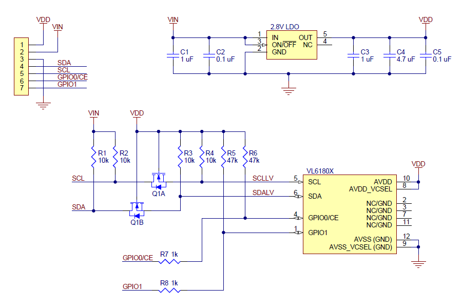
Also I am using these sensors with any arduino without problems, it does not seem like a voltage level issue. |
|
|
temtronic
Joined: 01 Jul 2010
Posts: 9130
Location: Greensville,Ontario
|
|
| Posted: Thu Apr 25, 2024 6:12 am |
|
|
hmm, so not a hardware problem....
post a short, complete program.
It might be that you've setup the I2C peripheral wrong ( 'too fast' ? )
get it working without the mux first !
10K pullups seem 'light' to me. I'd put 10K in parallel,so now 5K.
Old gray cells remember 5K for 5V, 3K for 3 volt VDD. |
|
|
bmete
Joined: 13 Jul 2023
Posts: 37
|
|
| Posted: Thu Apr 25, 2024 6:42 am |
|
|
My main code is very long, so I am only sharing the part relevant to this task and the definition codes above.
| Code: | #include <18F452.h>
#device ADC=10
#FUSES NOWDT
#define USE_TX_ISR
#use delay(crystal=20MHz)
#use rs232(baud=2400, xmit=PIN_C6, rcv=PIN_C7, parity=N, stop=1, bits=8, RECEIVE_BUFFER=128, ERRORS, TXISR)
#use i2c(Master, sda=PIN_C4, scl=PIN_C3)
#define TCA9548_ADDRESS1 0xE0 //70 default
#define VL6180X_ADDRESS 0x52 // 29 default
unsigned int8 n;
unsigned int8 n2;
unsigned int16 sensor_data;
unsigned int count = 0;
for (unsigned int i = 0x10; i < 0xFD; i+=2)
{
status = get_ack_status(i);
if (status == TRUE)
{
printf("ACK Address: %X\n\r", i);
count++;
delay_ms(2000);
}
}
void enable_bus(int8 n)
{
int8 bus = 0;
bit_set(bus,n);
i2c_start();
i2c_write(TCA9548_ADDRESS1);
i2c_write(bus);
i2c_stop();
}
void main()
{
setup_timer_1(T1_INTERNAL | T1_DIV_BY_8);
set_timer1(40536);
enable_interrupts(INT_timer1);
enable_interrupts(GLOBAL);
while(TRUE)
{
/* for (unsigned int i = 0x10; i < 0xFD; i+=2)
{
status = get_ack_status(i);
if (status == TRUE)
{
printf("ACK Address: %X\n\r", i);
count++;
delay_ms(2000);
}
}
*/
enable_bus(0);
i2c_start();
i2c_write(VL6180X_ADDRESS);
i2c_write((0x0066 >> 8) & 0xFF);
i2c_write(0x0066 & 0xFF);
sensor_data = i2c_read();
i2c_stop();
printf("%X\r\n", sensor_data);
}
}
|
Could you please check it for any mistakes?
| Quote: | | get it working without the mux first ! |
I am trying to do it but whenever I try the this part of the code, program resets.
| Code: | i2c_start();
i2c_write(VL6180X_ADDRESS);
i2c_write((0x0066 >> 8) & 0xFF);
i2c_write(0x0066 & 0xFF);
sensor_data = i2c_read();
i2c_stop();
printf("%X\r\n", sensor_data); |
| Quote: | 10K pullups seem 'light' to me. I'd put 10K in parallel,so now 5K.
Old gray cells remember 5K for 5V, 3K for 3 volt VDD. |
Thanks for the comment, I'll try it with the resistors which you advice. |
|
|
Ttelmah
Joined: 11 Mar 2010
Posts: 19255
|
|
| Posted: Thu Apr 25, 2024 9:09 am |
|
|
Using with an Arduino, does not rule out a voltage level problem at all.
Key big difference between the PIC and the Arduino, is the PIC has 'proper'
I2C voltage levels required on it's hardware, but the Arduino does not....
What you could try, is connecting to pins on your PIC that have TTL
(rather than Schmitt) buffers, and using software I2C on these. If this then
works, you have a solution. |
|
|
bmete
Joined: 13 Jul 2023
Posts: 37
|
|
| Posted: Thu Apr 25, 2024 10:35 am |
|
|
Hello ttelmah.
I’ll try what you said first thing tomorrow morning than I’ll feedback here.
For now I wonder something. Do you see any mistakes on my code? Do you think this is the right way to communicate with this sensor?
Thanks |
|
|
temtronic
Joined: 01 Jul 2010
Posts: 9130
Location: Greensville,Ontario
|
|
| Posted: Thu Apr 25, 2024 2:26 pm |
|
|
my quik look....
possible issue is I2C 'speed'.
I don't know what the default is if you don't specify, and don't know the speed of the peripheral.
This may not be the 'issue', but something to look at.
I HATE 'defaults'. Someones idea of what things should be configured almost always are NOT the 'faults' I need...... |
|
|
bmete
Joined: 13 Jul 2023
Posts: 37
|
|
| Posted: Fri Apr 26, 2024 3:05 am |
|
|
Hello
I don't know how to change the speed of the I2C or what speed I'm currently running it at.
| Code: | | #use i2c(MASTER, FAST, SCL=PIN_C3, SDA=PIN_C4) |
I tried both fast and slow here, the result is the same.
By the way, I haven't been able to test it with the i2c software yet, it was a little difficult since the chip is soldered to the card.
| Code: | i2c_start();
i2c_write(VL6180X_ADDRESS);
i2c_write((registerAddr >> 8) & 0xFF);
i2c_write(registerAddr & 0xFF); /
i2c_stop();
i2c_start();
i2c_write(VL6180X_ADDRESS | 0x01);
data = i2c_read();
i2c_stop(); |
I updated the code like this, the program constantly resets itself when I run it. |
|
|
PrinceNai
Joined: 31 Oct 2016
Posts: 462
Location: Montenegro
|
|
| Posted: Fri Apr 26, 2024 9:54 am |
|
|
Since I have an unfinished business with those TOF sensors, I tried to translate the code from an ST appnote. There are some functions to read and write to the chip and to do range measuring. Mind you, the code isn't tested since I don't have the hardware, all I know is it compiles without any remarks. Is someone has the time to look at those read and write functions with i2c_transfer functions, I'd appreciate it. One pin to pull the device out of reset should be added. Below is the code, ReadByte() function could help the OP
| Code: |
// ********************** HEADER ****************************
#include <18F46K22.h>
#device ADC=10
#FUSES NOWDT //No Watch Dog Timer
#FUSES DEBUG
#device ICD=TRUE
#use delay(internal=32000000)
#use rs232(baud=19200,parity=N,UART1,bits=8,stream=PORT1,errors)
#use i2c(Master,Slow,sda=PIN_C4,scl=PIN_C3,force_hw)
// ******************** DEFINITIONS****************************
#define VL6180_address 0x52 // 0x29 is default
int16 range;
// ******************* FUNCTIONS *****************************
// *********** WRITE ONE BYTE OF DATA TO VL6180 ***************
// Split 16-bit register address into two bytes and write
// the address + one byte of data via I2C
void WriteByte(unsigned int16 VL6180_register, char data) {
char data_write[3]; // create an array composed of register address and data
data_write[0] = (VL6180_register >> 8) & 0xFF;; // MSB of register address
data_write[1] = VL6180_register & 0xFF; // LSB of register address
data_write[2] = data & 0xFF; // data to write
i2c_transfer(VL6180_address, data_write, 3);
}
// *********** READ ONE BYTE OF DATA FROM VL6180 **************
// Split 16-bit register address into two bytes and write
// required register address to VL6180 and read the data back
char ReadByte(unsigned int16 VL6180_register) {
char data_write[2];
char data_read[1];
data_write[0] = (VL6180_register >> 8) & 0xFF; // MSB of register address
data_write[1] = VL6180_register & 0xFF; // LSB of register address
i2c_transfer_out(VL6180_address, data_write, 2); // send register address
i2c_transfer_in(VL6180_address, data_read, 1); // read data from it
return data_read[0]; // return requested data to the caller
}
// ****************** INIT VL6180 *****************************
void Init_VL6180 (void){
char reset;
reset = ReadByte(0x016);
if (reset == 1){ // check to see if VL6180 has been initialised already
// if not
// sensor calibration values, should be loaded on any sensor reset or power-up
// Mandatory : private registers
WriteByte(0x0207, 0x01);
WriteByte(0x0208, 0x01);
WriteByte(0x0096, 0x00);
WriteByte(0x0097, 0xfd);
WriteByte(0x00e3, 0x00);
WriteByte(0x00e4, 0x04);
WriteByte(0x00e5, 0x02);
WriteByte(0x00e6, 0x01);
WriteByte(0x00e7, 0x03);
WriteByte(0x00f5, 0x02);
WriteByte(0x00d9, 0x05);
WriteByte(0x00db, 0xce);
WriteByte(0x00dc, 0x03);
WriteByte(0x00dd, 0xf8);
WriteByte(0x009f, 0x00);
WriteByte(0x00a3, 0x3c);
WriteByte(0x00b7, 0x00);
WriteByte(0x00bb, 0x3c);
WriteByte(0x00b2, 0x09);
WriteByte(0x00ca, 0x09);
WriteByte(0x0198, 0x01);
WriteByte(0x01b0, 0x17);
WriteByte(0x01ad, 0x00);
WriteByte(0x00ff, 0x05);
WriteByte(0x0100, 0x05);
WriteByte(0x0199, 0x05);
WriteByte(0x01a6, 0x1b);
WriteByte(0x01ac, 0x3e);
WriteByte(0x01a7, 0x1f);
WriteByte(0x0030, 0x00);
// Recommended : Public registers - See data sheet for more detail
WriteByte(0x0011, 0x10); // Enables polling for 'New Sample ready' when measurement completes
WriteByte(0x010a, 0x30); // Set the averaging sample period (compromise between lower noise and increased execution time)
WriteByte(0x003f, 0x46); // Sets the light and dark gain (upper nibble). Dark gain should not be CHANGED.
WriteByte(0x0031, 0xFF); // sets the # of range measurements after which auto calibration of system is performed
WriteByte(0x0040, 0x63); // Set ALS integration time to 100ms
WriteByte(0x002e, 0x01); // perform a single temperature calibration of the ranging sensor
//Optional: Public registers - See data sheet for more detail
WriteByte(0x001b, 0x09); // Set default ranging inter-measurement period to 100ms
WriteByte(0x003e, 0x31); // Set default ALS inter-measurement period to 500ms
WriteByte(0x0014, 0x24); // Configures interrupt on 'New Sample Ready threshold event'
WriteByte(0x016, 0x00); //change fresh out of set status to 0
}
}
///////////////////////////////////////////////////////////////
// Start a range measurement in single shot mode
///////////////////////////////////////////////////////////////
void VL6180_Start_Range() {
WriteByte(0x018,0x01);
}
///////////////////////////////////////////////////////////////
// poll for new RANGE sample to be ready
///////////////////////////////////////////////////////////////
void VL6180_Poll_Range() {
char status;
char range_status;
status = ReadByte(0x04f); // check the status
range_status = status & 0x07;
while (range_status != 0x04) { // wait for new measurement ready status
status = ReadByte(0x04f);
range_status = status & 0x07;
delay_ms(1); // (can be removed)
}
}
///////////////////////////////////////////////////////////////
// Read range result (mm)
///////////////////////////////////////////////////////////////
int VL6180_Read_Range() {
int16 range;
range = ReadByte(0x062);
return range;
}
///////////////////////////////////////////////////////////////
// clear VL6180 interrupts
///////////////////////////////////////////////////////////////
void VL6180_Clear_Interrupts() {
WriteByte(0x015,0x07);
}
// ****************** INTERRUPTS *****************************
#INT_TIMER0
void TIMER0_isr(void)
{
}
#INT_RDA
void RDA_isr(void)
{
}
// ***************** END INTERRUPTS **************************
void main()
{
setup_timer_0(RTCC_INTERNAL|RTCC_DIV_8); //65,5 ms overflow
enable_interrupts(INT_TIMER0);
enable_interrupts(INT_RDA);
enable_interrupts(GLOBAL);
Init_VL6180(); // load settings onto VL6180X
while(TRUE)
{
VL6180_Start_Range(); // start single range measurement
VL6180_Poll_Range(); // poll the VL6180 till new sample ready
range = VL6180_Read_Range(); // read range result
VL6180_Clear_Interrupts(); // clear the interrupt on VL6180
// pc.printf("%d\r\n", range); // send range to pc by serial
delay_ms(100);
}
}
|
|
|
|
bmete
Joined: 13 Jul 2023
Posts: 37
|
|
| Posted: Tue Apr 30, 2024 12:48 am |
|
|
Hello PrinceNai
| Quote: | | Since I have an unfinished business with those TOF sensors, I tried to translate the code from an ST appnote. There are some functions to read and write to the chip and to do range measuring. Mind you, the code isn't tested since I don't have the hardware, all I know is it compiles without any remarks. Is someone has the time to look at those read and write functions with i2c_transfer functions, I'd appreciate it. One pin to pull the device out of reset should be added. Below is the code, ReadByte() function could help the OP |
First of all, thank you very much for sharing this code. I had the chance to try the code yesterday, unfortunately the messages from the sensor are not correct. However, this gave me an idea to run the sensor. As you wrote, I first added the init and default settings functions to my code. I examined the messages on both the PIC and the Arduino with Scope. Although the packages are exactly the same, the message returned from the sensor to the Arduino is correct, but either 0x00 or 0xFF is returned to the PIC.
There is definitely something I missed and I can't find it for days.
Actually, theoretically everything is clear, what I tried is to adapt the VL6180x_getRegister and VL6180x_setRegister functions in Arduino to the PIC. No matter how I tried, I couldn't achieve this. I would be very happy if someone here could help adapting these two functions for PIC.
| Code: | uint8_t VL6180x::VL6180x_getRegister(uint16_t registerAddr)
{
uint8_t data;
Wire.beginTransmission(_i2caddress); // Address set on class instantiation
Wire.write((registerAddr >> 8) & 0xFF); // MSB of register address
Wire.write(registerAddr & 0xFF); // LSB of register address
Wire.endTransmission(false); // Send address and register address bytes
Wire.requestFrom(_i2caddress, 1);
data = Wire.read(); // Read Data from selected register
return data;
}
void VL6180x::VL6180x_setRegister(uint16_t registerAddr, uint8_t data)
{
Wire.beginTransmission(_i2caddress); // Address set on class instantiation
Wire.write((registerAddr >> 8) & 0xFF); // MSB of register address
Wire.write(registerAddr & 0xFF); // LSB of register address
Wire.write(data); // Data/setting to be sent to device.
Wire.endTransmission(); // Send address and register address bytes
}
|
|
|
|
PrinceNai
Joined: 31 Oct 2016
Posts: 462
Location: Montenegro
|
|
| Posted: Tue Apr 30, 2024 4:06 am |
|
|
As I said, those two functions are questionable, read and write. Write should be ok, I do not know if I used those i2c_transfer_out and i2c_transfer_in correctly for read. Hopefully someone will point out if I made a mistake there and how to do it properly. Maybe like this:
| Code: |
char ReadByte2(unsigned int16 VL6180_register) {
char data_write[2];
char data_read[1];
data_write[0] = (VL6180_register >> 8) & 0xFF; // MSB of register address
data_write[1] = VL6180_register & 0xFF; // LSB of register address
i2c_transfer(VL6180_address, data_write, 2, data_read, 1); // send register address
return data_read[0]; // return requested data to the caller
}
|
|
|
|
bmete
Joined: 13 Jul 2023
Posts: 37
|
|
| Posted: Thu May 02, 2024 1:25 am |
|
|
Hello everyone,
I checked the message signals with the scope.
| Code: | i2c_start();
i2c_write(VL6180_address); // 0x52
i2c_write((0x0018 >> 8 ) & 0xFF);
i2c_write(0x0018 >> & 0xFF);
i2c_write(0x01);
i2c_stop();
delay_ms(10);
i2c_start();
i2c_write(VL6180_address);
i2c_write((0x0015 >> 8 ) & 0xFF);
i2c_write(0x0015 >> & 0xFF);
i2c_write(0x07);
i2c_stop();
i2c_start();
i2c_write(VL6180_address);
i2c_write((0x0062 >> 8 ) & 0xFF);
i2c_write(0x0062 >> & 0xFF);
i2c_stop();
i2c_start();
i2c_write(VL6180_address + 1); //0x53
sensor_data = i2c_read();
i2c_stop();
delay_ms(500); |
If I do not use the "i2c_read()" command you see on line 24 in the code above, the messages appear as in the first 3 images. Everything seems in order, but no answer of course.
If I use the "i2c_read()" command, things get crazy like in the from 4th to 8th picture.
1

2

3

4

5

6

7

8
 |
|
|
Ttelmah
Joined: 11 Mar 2010
Posts: 19255
|
|
| Posted: Thu May 02, 2024 4:32 am |
|
|
You normally cannot just read like that from I2C.
You have to select what register _first_, and then do a 'restart' to read.
Look at figure 33 in the datasheet for the VL6180, is shows exactly this.
It shows the device address, then the index being written, then a restart
device address set for read, and one or more reads.
Also, 'rethink' on the sections like this:
| Code: |
i2c_write((0x0062 >> 8 ) & 0xFF);
//This will always write 0, since 0x0062 (and the other values you use
//have 00 as their top byte. Something not right here......
//Also 'rethink, and use 'make8' to do this. Touch wood the compiler may
//be smart enough to automatically just be taking the top byte, but help
//it and use the CCS instruction - a lot more efficient if it isn't that smart.
i2c_write(0x0062 >> & 0xFF);
//Then something further is wrong here You don't have a value for how
//much to rotate. Have a nasty feeling this may be treated as a unary
//instruction. I don't think this should compile as posted.... :(
|
|
|
|
bmete
Joined: 13 Jul 2023
Posts: 37
|
|
| Posted: Thu May 02, 2024 9:14 am |
|
|
Ttelmah,
Based on what you said, I made some changes to the code. When I modified the code below, I was finally able to read the distance data from the sensor with the scope.
But I cannot read these values on the processor. It is always return zero.

| Code: | i2c_start();
i2c_write(VL6180X_ADDRESS);
i2c_write((0x0018 >> 8) & 0xFF);
i2c_write(0x0018 & 0xFF);
i2c_write(0x01);
i2c_stop();
delay_ms(10);
i2c_start();
i2c_write(VL6180X_ADDRESS);
i2c_write((0x0015 >> 8) & 0xFF);
i2c_write(0x0015 & 0xFF);
i2c_write(0x07);
i2c_stop();
i2c_start();
i2c_write(VL6180X_ADDRESS);
i2c_write((0x0062 >> 8) & 0xFF);
i2c_write(0x0062 & 0xFF);
i2c_start();
i2c_write(VL6180X_ADDRESS+1);
sensor_data1 = i2c_read(TRUE);
i2c_start();
i2c_write(VL6180X_ADDRESS+1);
sensor_data2 = i2c_read(TRUE);
i2c_stop();
printf("%x %x \r\n", sensor_data1, sensor_data2);
delay_ms(500); |
I tried the sensor_data variable as byte, unsigned int, char etc. and all of them return as zero.
I think I am writing data to the sensor in a correct way but, I can not read data from sensor. Do you have any idea about how to do?
By the way, I need to think more about the part you mentioned "rethink". |
|
|
|
|
You cannot post new topics in this forum
You cannot reply to topics in this forum
You cannot edit your posts in this forum
You cannot delete your posts in this forum
You cannot vote in polls in this forum
|
Powered by phpBB © 2001, 2005 phpBB Group
|

