 |
 |
| View previous topic :: View next topic |
| Author |
Message |
eddfish
Joined: 09 Dec 2019
Posts: 9
Location: United Kingdom


|
| SPI Slave Select Issue |
 Posted: Mon Dec 09, 2019 10:49 am Posted: Mon Dec 09, 2019 10:49 am |
 |
|
I'm having some issues with SPI on the DSPIC33EV256GM102, specifically slave select.
I have two DSPIC33EV256GM102's connected to a PIC18F as slaves, with the 18F as master.
A single master and slave works fine, however with two slaves connected, the system is behaving as if I have SS disabled on the slaves and appears to be triggering the #INT_SPI1 interrupt regardless of whether the line is SS line is high or low.
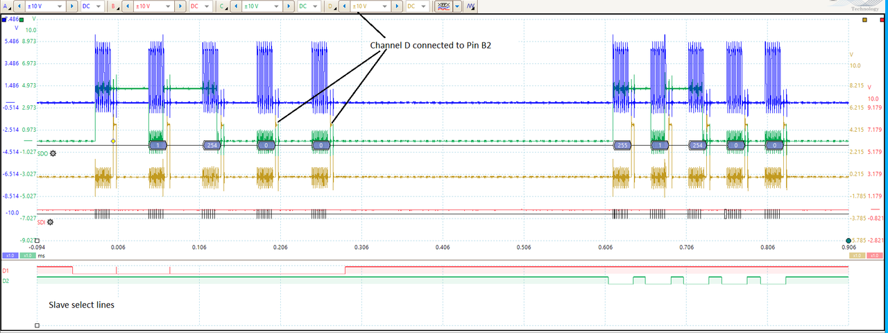
D1 and D2 are the slave select lines. I have tried (as you can see) dropping SS for several bytes or cycling it on and off for every transfer. It makes no difference either way.
I have set up Channel D to one of the slave's B2 pins (the yellow trace) so that pin goes high every time the #INT_SPI1 fires. D2 (green digital signal) is the SS for the chip in question.
We should (if I've understood correctly) see no reaction on channel D whilst D2 remains high, then get it working on the bytes to the right hand side of the image.
I realise this is probably something very obvious, and I apprecate the explanation may not be perfect, but right now I'm a little stuck.
| Code: | #include <33EV256GM102.h>
#use delay(clock=20M, crystal=20M)
#FUSES NOWDT //No Watch Dog Timer
#FUSES CKSFSM //Clock Switching is enabled, fail Safe clock monitor is enabled
#FUSES NOBROWNOUT //No brownout reset
#FUSES PROTECT //Copy Protection enabled
#BIT SLAVESELECT = 0x0242.7 //SPI1 Slave select enabled bit
#use spi(SLAVE, FORCE_HW, SPI1, BITS=8, stream=SPI_STREAM,) // uses hardware SPI and gives this stream the name SPI_STREAM
#define LED_1 PIN_B5 //C4
unsigned int8 serialdata=0;
#INT_SPI1
void spi_isr(void)
{
output_high(PIN_B2); //Diagnostic output, determines when SPI read occurs
serialdata = spi_xfer_in();
output_low(PIN_B2); //diagnostic output, determines SPI END
clear_interrupt(INT_SPI1);
}
void main()
{
set_TRIS_A(0b1111111111111111);
set_TRIS_B(0b1000001010000001);//B0 = CS, B7 = SCK, B8=SDO, B9 = SDI
enable_interrupts(INTR_GLOBAL); //
enable_interrupts(INT_SPI1);
clear_interrupt(INT_SPI1);
SLAVESELECT = 1; // FORCING SLAVE SELECT ACTIVE IN SPI - appears to make no difference.
delay_us(1);
start:
delay_us(1);
goto start;
} |
|
|
 |
temtronic
Joined: 01 Jul 2010
Posts: 9641
Location: Greensville,Ontario
|
|
| Posted: Mon Dec 09, 2019 11:43 am |
|
|
While I don't use that PIC, some general comments...
1) The 'scope' setup is wrong as signals should only go 0 to VDD (3 or 5 volts). What's shown is dang hard for an old guy like me to see let alone diagnose.
2) Post the MASTER code. Without it, again,'we', can't tell if you've misconfigured the PIC.....
3) What pullups are you using?
4) What's the VDD of the PICs ?
I'm sure others will respond.
Jay |
|
|
PCM programmer
Joined: 06 Sep 2003
Posts: 21708
|
|
| Posted: Mon Dec 09, 2019 1:18 pm |
|
|
Some dsPIC's have an errata for a non-working Slave Select. Your PIC
does not have that one, but it could still be there and not yet found or
documented. See the following dsPIC's errata.
dsPIC33FJ128GP706 errata:
http://ww1.microchip.com/downloads/en/DeviceDoc/80446f.pdf
See page 10 on the right side. |
|
|
Ttelmah
Joined: 11 Mar 2010
Posts: 20097
|
|
| Posted: Mon Dec 09, 2019 2:31 pm |
|
|
First, check the FRMEN bit. If this is enabled, SSEN does not work.
Then check the ANSEL registers. All the SPI bits have to be set to be digital
for the SSP to work.
| Quote: |
Note: All of the 4 pins of the SPIx serial interface
must be configured as digital in the
ANSELx registers.
|
From the data sheet.
It is quite likely that the SPI setup is missing the bit for the SS input. |
|
|
eddfish
Joined: 09 Dec 2019
Posts: 9
Location: United Kingdom
|
|
| Posted: Tue Dec 10, 2019 3:56 am |
|
|
First of all thank you all for your suggestions. It really is appreciated.
| Ttelmah wrote: | First, check the FRMEN bit. If this is enabled, SSEN does not work.
Then check the ANSEL registers. All the SPI bits have to be set to be digital
for the SSP to work.
|
I have tried the updated code below to try out the ANSEL and FRMEN suggestions. Unfortunately it doesn't seem to have made a difference.
| temtronic wrote: | While I don't use that PIC, some general comments...
1) The 'scope' setup is wrong as signals should only go 0 to VDD (3 or 5 volts). What's shown is dang hard for an old guy like me to see let alone diagnose.
2) Post the MASTER code. Without it, again,'we', can't tell if you've misconfigured the PIC.....
3) What pullups are you using?
4) What's the VDD of the PICs ?
|
VDD is 5V.
No pullups are currently being used. There isn't a potential issue at initialisation, data transmission doesn't happen for several seconds after start up.
I can trim down and post the master code if it would be useful, but the master is pulling the line up and down, data transmission works, it is only the slave select that doesn't work, but the master is defintely producing the SS signal, and those levels are being measured at the pin on the slave.
I have configured the picoscope slightly differently so that it is set to 5V max ranges. Noise makes this clip, and to me the overlappping signals are a little less clear when looking at logic levels, but see what you think.
I have also attached channel B (red) to the slave select line also connected to the D2 (green) digital scope input. This just helps to show nothing too weird is going on when you can see the whole trace:

| Code: | #include <33EV256GM102.h>
#use delay(clock=20M, crystal=20M)
#FUSES NOWDT //No Watch Dog Timer
#FUSES CKSFSM //Clock Switching is enabled, fail Safe clock monitor is enabled
#FUSES NOBROWNOUT //No brownout reset
#FUSES PROTECT //Copy Protection enabled
#BIT SLAVESELECT = 0x0242.7 //SPI1 Slave select enabled bit
#BIT FRMEN = 0x0244.15 //SPI1 FRMEN
#BIT ANSB0 = 0x0E22.0 //ANSEL B 0E22
#BIT ANSB1 = 0x0E22.1
#BIT ANSB2 = 0x0E22.2
#BIT ANSB3 = 0x0E22.3
#BIT ANSB7 = 0x0E22.7
#BIT ANSB8 = 0x0E22.8
#BIT ANSB9 = 0x0E22.9
#use spi(SLAVE, FORCE_HW, SPI1, BITS=8, stream=SPI_STREAM,) // uses hardware SPI and gives this stream the name SPI_STREAM
#define LED_1 PIN_B5 //C4
unsigned int8 serialdata=0;
#INT_SPI1
void spi_isr(void)
{
output_high(PIN_B2); //Diagnostic output, determines when SPI read occurs
serialdata = spi_xfer_in();
output_low(PIN_B2); //diagnostic output, determines SPI END
clear_interrupt(INT_SPI1);
}
void main()
{
set_TRIS_A(0b1111111111111111);
set_TRIS_B(0b1000001010000001);//B0 = CS, B7 = SCK, B8=SDO, B9 = SDI
enable_interrupts(INTR_GLOBAL); //
enable_interrupts(INT_SPI1);
clear_interrupt(INT_SPI1);
SLAVESELECT = 1; // FORCING SLAVE SELECT ACTIVE IN SPI - appears to make no difference.
FRMEN = 0; // FRMEN must be 0 when SS = 1
ANSB0 = 0; //SS
ANSB7 = 0; //SCK
ANSB8 = 0; //SDO
ANSB9 = 0; //SDI
delay_us(1);
start:
delay_us(1);
goto start;
} |
Also that is very interesting about possible errata. I would however absolutely like to exhaust any possible mistakes that I am making before condiering that it might be an issue with the chip. I'm still betting that I have got something wrong somewhere. |
|
|
Ttelmah
Joined: 11 Mar 2010
Posts: 20097
|
|
| Posted: Tue Dec 10, 2019 4:51 am |
|
|
OK.
Comments:
1) Use the stream name in your spi_xfer.
2) You don't need the clear_interrupt in the ISR, the compiler does this
automatically.
3) Your clear_interrupt after enabling the interrupt is again pointless. You
need to either clear before enabling, or just get rid of this.
Since you have enabled the interrupt the line before, if the interrupt
was set, the handler will be called.
4) Your TRIS settings on the SPI pins are wrong. The SPI peripheral
overrides the TRIS. Just leave the pins set as input.
Now, I have checked, and with the current compiler the posted code does
configure everything correctly. There is one possible 'question mark', over
one setting. In the data sheet it says that you should not set both the
primary and secondary prescale to 1:1. This does in one place have a
remark to say that it applies to master only, but in another place does
not say this. I note that the prescales are both set to 1:1. So, worth
changing one of these to rule this out.
If you are not using SPI2, try the experiment of using #PIN SELECT and
mapping this to the same pins, and then change the SPI setup to use
SPI2. If it behaves differently it may help to give a hint as to what is
going on. There are a couple of similar PIC's that have issues with the
SPI1 port.
Does your master device assert SS high before the PIC starts?. If not
this can be a problem. In this case a pullup should be fitted to the SS
line. It does need to be high before the SPI peripheral is started.
If this is not happening, setup the SPI using the 'NOINIT' option in
the configuration line, and then in the code wait for the SS line to go high.
Only once it is high, then wake the SPI peripheral. |
|
|
eddfish
Joined: 09 Dec 2019
Posts: 9
Location: United Kingdom
|
|
| Posted: Thu Dec 12, 2019 10:17 am |
|
|
| Ttelmah wrote: |
1) Use the stream name in your spi_xfer.
2) You don't need the clear_interrupt in the ISR, the compiler does this
automatically.
3) Your clear_interrupt after enabling the interrupt is again pointless. You
need to either clear before enabling, or just get rid of this.
Since you have enabled the interrupt the line before, if the interrupt
was set, the handler will be called.
4) Your TRIS settings on the SPI pins are wrong. The SPI peripheral
overrides the TRIS. Just leave the pins set as input. |
Thank you for your comments. I have made the suggested amendments above. I also had the thought of trying SPI2, unfortunately it doesn't seem to work, but not in the same way. The interrupt just never fires (channel D, yellow):

| Code: | #include <33EV256GM102.h>
#use delay(clock=20M, crystal=20M)
#FUSES NOWDT //No Watch Dog Timer
#FUSES CKSFSM //Clock Switching is enabled, fail Safe clock monitor is enabled
#FUSES NOBROWNOUT //No brownout reset
#FUSES PROTECT //Copy Protection enabled
#BIT SPI1EN = 0x0240.15 //SPI1 Enable
#BIT SPI2EN = 0x0260.15 //SPI2 Enable
#BIT SLAVESELECT1 = 0x0242.7 //SPI1 Slave select enabled bit
#BIT FRMEN1 = 0x0244.15 //SPI1 FRMEN
#BIT SLAVESELECT2 = 0x0262.7 //SPI2 Slave select enabled bit
#BIT FRMEN2 = 0x0264.15 //SPI2 FRMEN
#BIT ANSB0 = 0x0E22.0 //ANSEL B 0E22
#BIT ANSB1 = 0x0E22.1
#BIT ANSB2 = 0x0E22.2
#BIT ANSB3 = 0x0E22.3
#BIT ANSB7 = 0x0E22.7
#BIT ANSB8 = 0x0E22.8
#BIT ANSB9 = 0x0E22.9
#pin_select SS2IN=PIN_B0
#pin_select SDO2=PIN_B8
#pin_select SDI2=PIN_B9
#pin_select SCK2IN=PIN_B7
#use spi(SLAVE, FORCE_HW, SPI2, BITS=8, stream=SPI_STREAM,) // uses hardware SPI and gives this stream the name SPI_STREAM
#define LED_1 PIN_B5 //C4
unsigned int8 serialdata=0;
#INT_SPI2
void spi_isr(void)
{
output_high(PIN_B2);
serialdata = spi_xfer_in(SPI_STREAM);
output_low(PIN_B2);
}
void main()
{
//set_TRIS_A(0b1111111111111111);
//set_TRIS_B(0b1000001010000001);//B0 = CS, B7 = SCK, B8=SDO, B9 = SDI
enable_interrupts(INTR_GLOBAL); //
enable_interrupts(INT_SPI2);
//SLAVESELECT1 = 1; // FORCING SLAVE SELECT ACTIVE IN SPI - appears to make no difference.
//FRMEN1 = 0; // FRMEN must be 0 when SS = 1
SLAVESELECT2 = 1;
FRMEN2 = 0;
ANSB0 = 0; //SS
ANSB7 = 0; //SCK
ANSB8 = 0; //SDO
ANSB9 = 0; //SDI
delay_us(1);
start:
while(input (PIN_B0)){
}
while(!input (PIN_B0)){
delay_us(1);
}
goto start;
} |
|
|
|
eddfish
Joined: 09 Dec 2019
Posts: 9
Location: United Kingdom
|
|
| Posted: Thu Dec 12, 2019 10:40 am |
|
|
I then tried a bit of a hack, more as a sense check than anything else. Back to using SPI1, I just ran a pair of while loops continuously checking the status of the SS pin. When its high it just disables the SPI module (sets SPIEN to 0), when its low, the SPI module is enabled.
It works seemingly as intended. No interrupts when SS is high, (left of the image) but an interrupt after each byte on the right hand side (when SS is low).
Whilst I appreciate there are probably a list of reasons not to do this as long as my arm (as well as the fact that the main loop is currently entirely just checking a pin) it does at hopefully least to some extent show that hardware wise the connections are OK, the levels are OK etc.
I am however a bit stuck as to what to do next, so any suggestions would be appreciated.

| Code: | #include <33EV256GM102.h>
#use delay(clock=20M, crystal=20M)
#FUSES NOWDT //No Watch Dog Timer
#FUSES CKSFSM //Clock Switching is enabled, fail Safe clock monitor is enabled
#FUSES NOBROWNOUT //No brownout reset
#FUSES PROTECT //Copy Protection enabled
#BIT SPI1EN = 0x0240.15 //SPI1 Enable
#BIT SPI2EN = 0x0260.15 //SPI2 Enable
#BIT SLAVESELECT1 = 0x0242.7 //SPI1 Slave select enabled bit
#BIT FRMEN1 = 0x0244.15 //SPI1 FRMEN
#BIT SLAVESELECT2 = 0x0262.7 //SPI2 Slave select enabled bit
#BIT FRMEN2 = 0x0264.15 //SPI2 FRMEN
#BIT ANSB0 = 0x0E22.0 //ANSEL B 0E22
#BIT ANSB1 = 0x0E22.1
#BIT ANSB2 = 0x0E22.2
#BIT ANSB3 = 0x0E22.3
#BIT ANSB7 = 0x0E22.7
#BIT ANSB8 = 0x0E22.8
#BIT ANSB9 = 0x0E22.9
//#pin_select SS2IN=PIN_B0
//#pin_select SDO2=PIN_B8
//#pin_select SDI2=PIN_B9
//#pin_select SCK2IN=PIN_B7
#use spi(SLAVE, FORCE_HW, SPI1, BITS=8, stream=SPI_STREAM,) // uses hardware SPI and gives this stream the name SPI_STREAM
#define LED_1 PIN_B5 //C4
unsigned int8 serialdata=0;
#INT_SPI1
void spi_isr(void)
{
output_high(PIN_B2);
serialdata = spi_xfer_in(SPI_STREAM);
output_low(PIN_B2);
}
void main()
{
//set_TRIS_A(0b1111111111111111);
//set_TRIS_B(0b1000001010000001);//B0 = CS, B7 = SCK, B8=SDO, B9 = SDI
enable_interrupts(INTR_GLOBAL); //
enable_interrupts(INT_SPI1);
SLAVESELECT1 = 1; // FORCING SLAVE SELECT ACTIVE IN SPI - appears to make no difference.
FRMEN1 = 0; // FRMEN must be 0 when SS = 1
//SLAVESELECT2 = 1;
//FRMEN2 = 0;
ANSB0 = 0; //SS
ANSB7 = 0; //SCK
ANSB8 = 0; //SDO
ANSB9 = 0; //SDI
delay_us(1);
start:
while(input (PIN_B0)){
SPI1EN=0;
}
while(!input (PIN_B0)){
SPI1EN=1;
delay_us(1);
}
goto start;
} |
|
|
|
eddfish
Joined: 09 Dec 2019
Posts: 9
Location: United Kingdom
|
|
| Posted: Fri Dec 13, 2019 8:29 am |
|
|
I forgot to mention earlier that I also did try the suggestion about the primary/secondary prescale.
I tried running:
| Code: | | #use delay(clock=40M, crystal=20M) |
It makes no difference. Slave select still does nothing. |
|
|
temtronic
Joined: 01 Jul 2010
Posts: 9641
Location: Greensville,Ontario
|
|
| Posted: Fri Dec 13, 2019 8:45 am |
|
|
OK I don't use that pic but some 'random' thoughts....
1) nornally you don't select the 'PROTECT' fuse until project goe out the door.
2) best to use getenv(...) than hard coding the registers
3) I see #pin_select, maybe the defaults aren't what you think
4) normally you need to disable EVERY other peripheral associated with pins except the one you need.
5) others might comment on the goto start as being bad Maybe change to do while(1) syntax ? the code shouldn't change but.......
6) maybe get rid of //lines of code, reduces 'eye clutter'
7) I'd add fuse PUT.... also a delay_ms(500) in MAIN() before enabling the interrupts. While 'technically' not needed it ensures PIC is configured and READY to do stuff. |
|
|
Ttelmah
Joined: 11 Mar 2010
Posts: 20097
|
|
| Posted: Fri Dec 13, 2019 12:06 pm |
|
|
Try adding:
setup_adc_ports(NO_ANALOGS);
and
setup_comparator(2, NC_NC);
(keep the ANSEL settings as well.
I still think the analog function is not being disabled, so the pin can't
function as the slave input. Making 'sure' everything analog is off, is a
essential part on these chips, and I'm wondering is something is
not actually getting turned off....
However this is interesting:
<https://www.microchip.com/forums/m194972.aspx>
Though the poster is talking initially about a PIC24, at the end he
is saying that the bug also applies to a 33F. |
|
|
Ttelmah
Joined: 11 Mar 2010
Posts: 20097
|
|
| Posted: Sun Dec 15, 2019 8:47 am |
|
|
Try one more thing:
| Code: |
#word SPI1CON2=getenv("SFR:SPI2CON2")
SPI2FSD=SPICON2.13
//change to SPI1 if using SPI1
SPI2FSD=1; //in your initialisation
|
Have just had a 'play' with a PIC 24, talking to a PIC 33 slave, and the SS
line would not work, till I set this bit. This is the direction control for the
frame sync, which shares the SS pin. The data sheet makes no mention
of it being needed for SS, but lo and behold, it seems to affect the SS pin!....
It defaults to 0, which sets the pin as output from the peripheral.
Since #USE does not offer SS, I was setting up with:
| Code: |
#define SPI_MODE_0 (SPI_L_TO_H | SPI_XMIT_L_TO_H)
#define SPI_MODE_1 (SPI_L_TO_H)
#define SPI_MODE_2 (SPI_H_TO_L)
#define SPI_MODE_3 (SPI_H_TO_L | SPI_XMIT_L_TO_H)
setup_spi2(SPI_SLAVE | SPI_MODE_0 | SPI_CLK_DIV_4 | SPI_SLAVE | SPI_SS_ENABLED);
|
I put this on a bus with a second hardware SPI chip, and both are merrily
talking without clashing. |
|
|
eddfish
Joined: 09 Dec 2019
Posts: 9
Location: United Kingdom
|
|
| Posted: Mon Dec 16, 2019 8:30 am |
|
|
This is a great find, and I really seriously appreciate you trying it out.
Unfortunately (if I have understood correctly) even with this implemented it still doesn't work.
I had a look at the datasheet and for the DSPIC33EV256GM102 the SPIFSD control bit (for SPI1) is bit 14 at address 0244.
I ran this:
| Code: |
#BIT SPIFSD1 = 0x0244.14 //SPI1 FSD
(in the main)
SPIFSD1 = 1; //Frame Sync pulse input (slave)
|
Have I interpreted what you were suggesting correctly here?
I appreciate your suggestion of using getenv, which I will implement when working, and I appreciate will make porting to another chip immensely easier, but right now hard coding (unless I'm missing something) seems simpler.
I tried a load of other stuff, but then I tried using setup_spi() instead of #USE SPI..
BINGO it fires the interrupt when SS is low and doesn't otherwise. Awesome.
I then tried taking away every mod I have made and stripping it right back. It still works perfectly seemingly.
The problem I am left with however is that in the full version of my code, I am using functions within #USE SPI (specifically spi_prewrite and spi_xfer_in). I find the additional functionality of #USE SPI fantastic, despite no real desire to use anything other than hardware pins.
I notice that you wrote: | Ttelmah wrote: | Try one more thing:
Since #USE does not offer SS
|
Does this mean that Slave Select doesn't work with #USE SPI even when using hardware? If so, I really have tried to read the manual thoroughly and can't find any mention of this?
Thanks again for everyone's help. |
|
|
eddfish
Joined: 09 Dec 2019
Posts: 9
Location: United Kingdom
|
|
| Posted: Wed Dec 18, 2019 11:02 am |
|
|
So I think I have found the issue, it has taken many hours but hopefully this helps somebody else in the future.
| Code: | | #use spi(SLAVE, FORCE_HW, ENABLE=PIN_B0, SPI1, BITS=8, stream=SPI_STREAM,) // uses hardware SPI and gives this stream the name SPI_STREAM |
Fixes it. The important thing seems to be that ENABLE=PIN_B0 is needed for a slave device to enable Slave Select with #USE SPI, despite hardware pins already being selected. Unless I have really missed it, this just isn't mentioned in the manual at all.
It seems obvious now that "ENABLE" might also mean Slave Select, but I had assumed that if FORCE HW was enabled, not requiring SCK, SDO or SDI to be specified, SS would also not need to be specified...
Well you know what they say about assumptions. |
|
|
temtronic
Joined: 01 Jul 2010
Posts: 9641
Location: Greensville,Ontario
|
|
| Posted: Wed Dec 18, 2019 12:02 pm |
|
|
arrrrrrgh ! What's in a name ?? It's really too bad that CCS used 'ENABLE' as a keyword for SPI devices. I've never seen 'enable' as a pin name. Sure 'enable' is on RS-485 devices, so maybe it's just a 'carry over' that the programmer used ?
Dang frustating to say the least.
Mighty happy you're 'up and running' though !! Got ANY hair left ?? |
|
|
|
|
You cannot post new topics in this forum
You cannot reply to topics in this forum
You cannot edit your posts in this forum
You cannot delete your posts in this forum
You cannot vote in polls in this forum
|
Powered by phpBB © 2001, 2005 phpBB Group
|

