 |
 |
| View previous topic :: View next topic |
| Author |
Message |
RaptorUK
Joined: 30 Apr 2019
Posts: 19


|
| USB with 18F2550 |
 Posted: Tue Apr 30, 2019 6:02 am Posted: Tue Apr 30, 2019 6:02 am |
 |
|
Using CCS PCH 5.015
I've been lurking here for some time and reading posts, many of which have helped me, but now I think I'm in need of some specific help.
I've recently resurrected a project that I originally worked on at the tail end of 2017, at that time I was using a "Dev" board made by MikroE, I had running code to capture 50 bytes of data sent every 200mS using 9bit RS232 comms, the 9th bit is used to signify the start of the block. I also had I2C working which was used to talk to a RTC and an EEPROM. The 50 bytes of status data was relayed out via the USB to a PC running LabVIEW and TestStand.
Fast forward to today and I now have my own board with the PIC 18F2550 and some other bits and pieces on it which means I have been able to use this board for other projects.
This has been my first PIC coding project, I've not done the best job, I sill have a lot to learn, but I have something which kinda works, sometimes, it's a little flaky and it's this flaky-ness I'm trying to understand and eliminate.
The issue I'm seeing involves the USB "com port" becoming inaccessible and needed a PIC power cycle for it to come back . . . when the USB is inaccessible it is still shown in Device Manager and the PIC is still running, I have red LED that flashes when a status block of 50 bytes is ready, but my LabVIEW code will not see the com port neither will RealTerm . . .
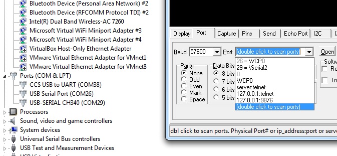
I'm hoping that the fact that the Device Manager still "sees" the device but Realterm and LabVIEW don't will mean something significant to help me fix my issue. I'm not knowledgeable enough with USB to understand what is going on here.
I have recently been wondering if it's a Stack issue but mt .lst file says this . . .
ROM used: 9174 bytes (28%)
Largest free fragment is 23594
RAM used: 699 (34%) at main() level
743 (36%) worst case
Stack used: 18 locations (9 in main + 9 for interrupts)
Stack size: 31
. . . which I think looks OK ?
I originally had my own functions to clear FERR and OERR which I have since removed and am now relying on "ERRORS" in my RS232 stream definition
| Code: | | #use rs232(baud=9600, parity=N, xmit=PIN_C6, rcv=PIN_C7, bits=9, stream=RX, ERRORS ) |
Funnily enough . . . while composing this message I think I may have stumbled across my issue, I didn't have
I've just added this and the flakyness has gone, I'll keep testing and report back in a day or two, I thought I'd still post this message, it might help someone else.
Oh, and the reason I think the FUSE was missing, I originally created my project without USB and added USB subsequently, so I think It's my fault not the Project Wizard. |
|
 |
Ttelmah
Joined: 11 Mar 2010
Posts: 20112
|
|
| Posted: Tue Apr 30, 2019 7:04 am |
|
|
VREGEN, enables the voltage regulator used to feed the I2C transceivers.
You can run without this, _provided_ you feed 3.3v into the Vusb pin.
If you don't feed this and the regulator is not on, the USB transceivers
won't be getting power. Not surprised it'll be 'flaky'... |
|
|
RaptorUK
Joined: 30 Apr 2019
Posts: 19
|
|
| Posted: Tue Apr 30, 2019 9:14 am |
|
|
| Ttelmah wrote: | VREGEN, enables the voltage regulator used to feed the I2C transceivers.
You can run without this, _provided_ you feed 3.3v into the Vusb pin.
If you don't feed this and the regulator is not on, the USB transceivers
won't be getting power. Not surprised it'll be 'flaky'... |
Yep, in hindsight, it's a surprise it worked as "well" as it did . . . it's much. much better now, I can at least continue debugging. |
|
|
Ttelmah
Joined: 11 Mar 2010
Posts: 20112
|
|
| Posted: Tue Apr 30, 2019 10:25 am |
|
|
I suspect what was happening, was classic for a driver that is not powered.
The internal diodes in the output FET's were acting as diodes when reverse
biased, so the signal on the USB bus would at times charge Vusb up
to only perhaps 0.7v below the voltage it needed.... |
|
|
RaptorUK
Joined: 30 Apr 2019
Posts: 19
|
| Re: USB with 18F2550 |
| Posted: Tue May 07, 2019 5:16 am |
|
|
| RaptorUK wrote: |
I've just added this and the flakyness has gone, I'll keep testing and report back in a day or two, I thought I'd still post this message, it might help someone else.
Oh, and the reason I think the FUSE was missing, I originally created my project without USB and added USB subsequently, so I think It's my fault not the Project Wizard. |
While things seem to be better I'm still getting the issue where LabVIEW and Realterm cannot see the Com port even though it's still showing in Device Manager, anyone any idea what might be causing this behaviour ?
In Device Manager if I "scan for hardware changes" the port is still show and Realterm still cannot see it, I have to physically unplug the USB from my board and reconnect it. |
|
|
Ttelmah
Joined: 11 Mar 2010
Posts: 20112
|
|
| Posted: Tue May 07, 2019 6:20 am |
|
|
Have you got 'connection sense' wired and used in the PIC code?.
This is _required_ if the device is not powered by the USB bus.
The CCS notes in the files make it sound 'optional'. It isn't. USB requires
the device to turn it's drivers off, if Vusb goes off. If this is not done, and
Windows puts the USB bus to sleep, it won't wake back up.
You can partially disable this, by in the Windows device manager looking
for the setting for the USB device called 'Selective suspend', and disabling
this. However Windows will still use this if it goes fully into hibernate
mode.
The other thing that can cause an issue for LabView is incorrect settings
in the NI-VISA driver:
<https://knowledge.ni.com/KnowledgeArticleDetails?id=kA00Z000000P6soSAC> |
|
|
RaptorUK
Joined: 30 Apr 2019
Posts: 19
|
|
| Posted: Tue May 07, 2019 7:26 am |
|
|
Thanks for the reply.
| Ttelmah wrote: | Have you got 'connection sense' wired and used in the PIC code?.
This is _required_ if the device is not powered by the USB bus.
The CCS notes in the files make it sound 'optional'. It isn't. USB requires
the device to turn it's drivers off, if Vusb goes off. If this is not done, and
Windows puts the USB bus to sleep, it won't wake back up. |
I'm not using connection sense as my board is currently only being powered by USB.
| Ttelmah wrote: | You can partially disable this, by in the Windows device manager looking for the setting for the USB device called 'Selective suspend', and disabling
this. However Windows will still use this if it goes fully into hibernate
mode. |
I've already disabled Selective Suspend in my Power Option.
| Ttelmah wrote: | The other thing that can cause an issue for LabView is incorrect settings
in the NI-VISA driver:
<https://knowledge.ni.com/KnowledgeArticleDetails?id=kA00Z000000P6soSAC> |
I'm using VISA version 16.0, the port is there but I "lose" it part way through a test. |
|
|
Ttelmah
Joined: 11 Mar 2010
Posts: 20112
|
|
| Posted: Tue May 07, 2019 8:09 am |
|
|
Are you calling usb_task reasonably regularly in your code?. Again this is
'required'. Usb_task handles some parts of the housekeeping in USB. It is
what will re-make the connection if Windows does send a disconnect, and
it also ensures some other parts of the interface are kept correctly
synchronised. It must be called occasionally or the interface can get into
an unresponsive state. |
|
|
RaptorUK
Joined: 30 Apr 2019
Posts: 19
|
|
| Posted: Tue May 07, 2019 8:36 am |
|
|
| Ttelmah wrote: | Are you calling usb_task reasonably regularly in your code?. Again this is
'required'. Usb_task handles some parts of the housekeeping in USB. It is
what will re-make the connection if Windows does send a disconnect, and
it also ensures some other parts of the interface are kept correctly
synchronised. It must be called occasionally or the interface can get into
an unresponsive state. |
I estimate that at worst I'm calling it every 0.5mS unless I'm missing somewhere in my code where I'm getting stalled for a while. |
|
|
Ttelmah
Joined: 11 Mar 2010
Posts: 20112
|
|
| Posted: Tue May 07, 2019 11:02 am |
|
|
OK. That should be alright.
Post your setup (fuses, clock etc..).
Describe your power connection, and the wiring to the USB connector.
Length, how is it connected?.
What smoothing have you got on Vusb, and on the PIC itself.
Your problem sounds as if there is a hardware issue. |
|
|
RaptorUK
Joined: 30 Apr 2019
Posts: 19
|
|
| Posted: Wed May 08, 2019 1:57 am |
|
|
Thanks for your help . . . .
| Ttelmah wrote: | OK. That should be alright.
Post your setup (fuses, clock etc..). |
This is my setup, some added by the Wizard some by me . . .
| Code: | #include <18F2550.h>
#device ADC=16
#FUSES NOWDT //No Watch Dog Timer
#FUSES NOBROWNOUT //No brownout reset
#FUSES NOLVP //No low voltage prgming, B3(PIC16) or B5(PIC18) used for I/O
#FUSES NOXINST //Extended set extension and Indexed Addressing mode disabled (Legacy mode)
#FUSES VREGEN // ENable 3.3 Voltage REGulator
#use delay(clock=48000000, crystal=8000000, USB)
// RX stream is for 9 bit comms
#use rs232(baud=9600, parity=N, xmit=PIN_C6, rcv=PIN_C7, bits=9, stream=RX, ERRORS )
// Slow should be 100kHz ? Fast is 400kHz ?
#use i2c(Master, SLOW, sda=PIN_B0, scl=PIN_B1, restart_wdt, FORCE_HW ) |
Maybe adding VRGEN didn't actually help with my flakiness, reading the data sheet it is enabled by default.
I have an 8MHz crystal (ABLS2-8.000MHZ-D4Y-T) with 2x 27pF caps
| Ttelmah wrote: | Describe your power connection, and the wiring to the USB connector.
Length, how is it connected?. |
Power is from USB only at the moment, I have facility to get power from an on-board 5V regulator and 24V but I'm not using that at the moment and can cope with just running from USB.
Wiring to the USB connector on the PCB is approx 50mm long, I have a surface mounted USB mini socket.
| Ttelmah wrote: | What smoothing have you got on Vusb, and on the PIC itself.
Your problem sounds as if there is a hardware issue. |
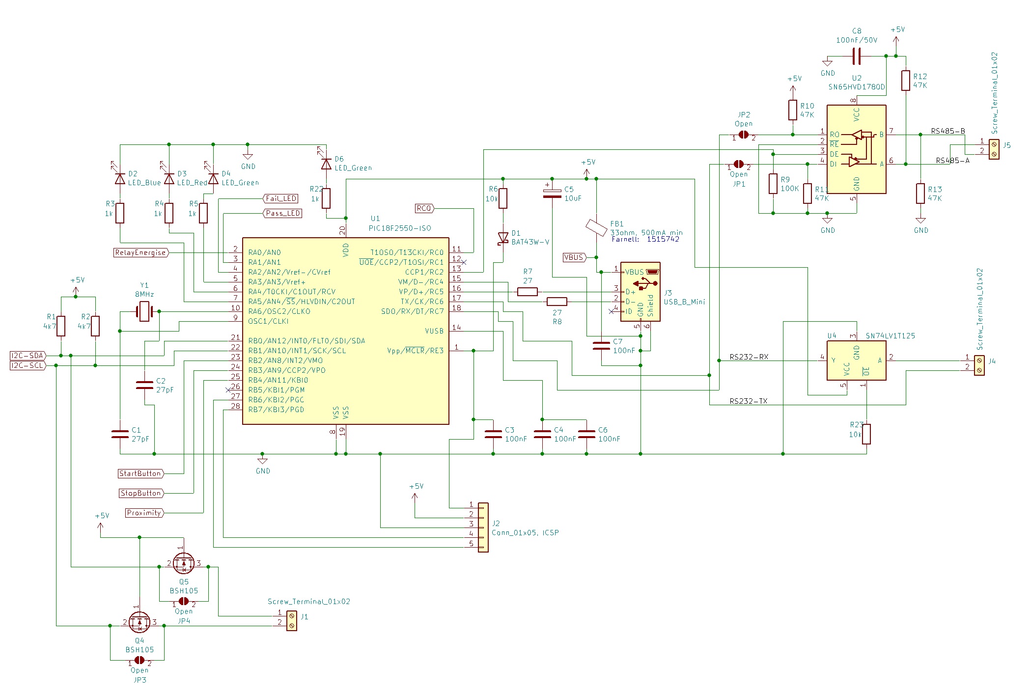
Please see attached picture showing part of my circuit diagram, RS485 transceiver in the top right is not fitted.
I wouldn't disagree with you that it might be hardware, the only thing that makes me think otherwise is the fact that for much of the time while my Teststand sequence is running I have no problems, it's when my RS22 comms stops and my device under test is being switched from mains to battery that I tend to get issues with my board's USB. This morning I'm going to create a few Teststand sequences to try and focus in on what is happening at the point where I get USB issues, hopefully I can make it fail on demand and then have a better understanding of when it occurs which might them lead to why it occurs.
 |
|
|
Ttelmah
Joined: 11 Mar 2010
Posts: 20112
|
|
| Posted: Wed May 08, 2019 2:29 am |
|
|
You only seem to have a 10uF on the Vbus across the processor. You must
have a smaller non electrolytic capacitor also across this (say 100nF). On
capacitors, 'bigger is not always better'. Electrolytic capacitors give a lot
of capacitance, but have very poor HF performance (up in the MHz range).
Small ceramic or polyester capacitors offer little capacitance, but have really
good HF performance. It is that HF performance, that suppresses the RF
spikes. Essential. This is why you should always have a capacitor like a
100nF, as close to the processor power pins as possible.
Then, why the 33R resistor?. This will be dropping a significant voltage.
If your circuit draws just 20mA, the drop across this would be 0.66v.
If you are worried about safety here just add a small fuse, but get rid
of this resistor.
Then you have 2*100nF for the Vusb. This is low. From the data sheet,
minimum capacitor value is 220nF. _Minimum_..... |
|
|
RaptorUK
Joined: 30 Apr 2019
Posts: 19
|
|
| Posted: Wed May 08, 2019 3:07 am |
|
|
| Ttelmah wrote: | You only seem to have a 10uF on the Vbus across the processor. You must
have a smaller non electrolytic capacitor also across this (say 100nF). On
capacitors, 'bigger is not always better'. Electrolytic capacitors give a lot
of capacitance, but have very poor HF performance (up in the MHz range).
Small ceramic or polyester capacitors offer little capacitance, but have really
good HF performance. It is that HF performance, that suppresses the RF
spikes. Essential. This is why you should always have a capacitor like a
100nF, as close to the processor power pins as possible. |
C7 is also effectively across VBUS, it's 100nF ceramic chip SMD.
| Ttelmah wrote: | Then, why the 33R resistor?. This will be dropping a significant voltage.
If your circuit draws just 20mA, the drop across this would be 0.66v.
If you are worried about safety here just add a small fuse, but get rid
of this resistor. |
It's a Ferrite Bead, it's 0.025 ohm at DC and 33ohm at 100MHz, it's the implementation that I borrowed from the development board I was using.
| Ttelmah wrote: | | Then you have 2*100nF for the Vusb. This is low. From the data sheet, minimum capacitor value is 220nF. _Minimum_..... |
I'll see what we have in stock and change one or both these caps to something larger. |
|
|
RaptorUK
Joined: 30 Apr 2019
Posts: 19
|
|
| Posted: Wed May 08, 2019 6:11 am |
|
|
| RaptorUK wrote: | | This morning I'm going to create a few Teststand sequences to try and focus in on what is happening at the point where I get USB issues, hopefully I can make it fail on demand and then have a better understanding of when it occurs which might them lead to why it occurs. |
So I've created a new test sequence in Teststand and have found the sequence of events that cause my USB to go haywire, it's when the device being tested is powered down from mains and then powered up from battery ( there is a switch on board to trigger the power up from battery ).
If I physically disconnect from the RS232 comms during the battery powerup and then reconnect once powered up everything works . . . interestingly just pulling the EO high on my SN74LV1T125 during the battery power up phase is not enough to prevent an issue.
I also tried adding an additional 100nF ceramic across VDD and VSS right by the PIC, didn't help.
Will add another 100nF to the VUSB next . . .
So this is looking more and more like an electronics issue, so not really pertinent to this forum any longer . . . I'll let you know when I fix it or find a suitably robust workaround.
Thanks again for the help |
|
|
Ttelmah
Joined: 11 Mar 2010
Posts: 20112
|
|
| Posted: Wed May 08, 2019 6:35 am |
|
|
I'm confused now. You are talking about some other device?.
You said this unit was powered by the USB.
Is this some other device attached to this part?. |
|
|
|
|
You cannot post new topics in this forum
You cannot reply to topics in this forum
You cannot edit your posts in this forum
You cannot delete your posts in this forum
You cannot vote in polls in this forum
|
Powered by phpBB © 2001, 2005 phpBB Group
|

