 |
 |
| View previous topic :: View next topic |
| Author |
Message |
Stephanfo
Joined: 28 Nov 2004
Posts: 5


|
| Library to program/verify a microchip PIC12F629/675 |
 Posted: Tue Apr 25, 2006 2:41 am Posted: Tue Apr 25, 2006 2:41 am |
 |
|
Hi all,
I wrote this library to allow you to program PIC12F629/675 from another microcontroller.
This library will allow you to make a PIC duplicator or a standalone programmer. I make this library for my company, to include the programing step with the product tester.
This library also calculate the 16bits checksum like MPLAB.
The two microcontrollers are directly connected, only an external circuit is needed to change the voltage from 5V to 12V (with a NPN and PNP for example).
| Code: | ////////////////////////////////////////////////////////////////////////////
//// ISPROG.c ////
//// Library to program/verify a microchip PIC12F629/675 ////
//// ////
////////////////////////////////////////////////////////////////////////////
/********************************************************
* Start of the config *
********************************************************/
// Assign connection between programer and microcontroleur
// It's possible to reverse the signal by set TRUE the reverse mode
#define ISPROG_MCLR_PIN PIN_C5
#define ISPROG_MCLR_REV FALSE
#define ISPROG_VCC_PIN PIN_E0
#define ISPROG_VCC_REV FALSE
#define ISPROG_DATA_PIN PIN_E1
#define ISPROG_DATA_REV FALSE
#define ISPROG_CLOCK_PIN PIN_E2
#define ISPROG_CLOCK_REV FALSE
// Slower coef in case CLOCK > 40MHz, set 2 or more
#define ISPROG_SLOWER 1
/********************************************************
* End of the config *
********************************************************/
#define ISPROG_MCLR_HIGH output_bit(ISPROG_MCLR_PIN, !ISPROG_MCLR_REV)
#define ISPROG_MCLR_LOW output_bit(ISPROG_MCLR_PIN, ISPROG_MCLR_REV)
#define ISPROG_VCC_HIGH output_bit(ISPROG_VCC_PIN, !ISPROG_VCC_REV)
#define ISPROG_VCC_LOW output_bit(ISPROG_VCC_PIN, ISPROG_VCC_REV)
#define ISPROG_DATA_HIGH output_bit(ISPROG_DATA_PIN, !ISPROG_DATA_REV)
#define ISPROG_DATA_LOW output_bit(ISPROG_DATA_PIN, ISPROG_DATA_REV)
#define ISPROG_CLOCK_HIGH output_bit(ISPROG_CLOCK_PIN, !ISPROG_CLOCK_REV)
#define ISPROG_CLOCK_LOW output_bit(ISPROG_CLOCK_PIN, ISPROG_CLOCK_REV)
#if ISPROG_DATA_REV == FALSE
#define ISPROG_DATA_READ input(ISPROG_DATA_PIN)
#else
#define ISPROG_DATA_READ !input(ISPROG_DATA_PIN)
#endif
// Command mapping
#define ISPROG_READ_PROG_COMMAND 0b00000100
#define ISPROG_READ_MEM_COMMAND 0b00000101
#define ISPROG_INCREMENT_COMMAND 0b00000110
#define ISPROG_LOADCONFIG_COMMAND 0b00000000
#define ISPROG_ERASEPROG_COMMAND 0b00001001
#define ISPROG_ERASEMEM_COMMAND 0b00001011
#define ISPROG_LOADPROG_COMMAND 0b00000010
#define ISPROG_LOADMEM_COMMAND 0b00000011
#define ISPROG_PROGINTERNAL_COMMAND 0b00001000
#define ISPROG_PROGEXTERNAL_COMMAND 0b00011000
#define ISPROG_ENDPROGEXT_COMMAND 0b00001010
// Constant to identify the device
#define ISPROG_UC_ID_ADDRESS 0x06
#define ISPROG_UC_629_ID 0x0F80
#define ISPROG_UC_675_ID 0x0FC0
#define ISPROG_UC_630_ID 0x10C0
#define ISPROG_UC_676_ID 0x10E0
// Constant to determine the revision
#define ISPROG_UC_REV_MASK 0x001F
// Memory size
#define ISPROG_PROG_SIZE 0x0400
#define ISPROG_EEPROM_SIZE 0x0080
// Calibration word address
#define ISPROG_OSCCAL_ADDRESS 0x03FF
// Configuration bit address
#define ISPROG_CONFIG_ADDRESS 0x07
#define ISPROG_CONFIG_UTIL_MASK 0x01FF
#define ISPROG_CONFIG_SAVE_MASK 0x3000
// Variable to save important register/config
int16 ISPROG_osccal_value = 0x3FFF;
int16 ISPROG_config_word = 0x3000;
// Variable to know the actual memory position and programming state
int16 ISPROG_Current_Address = 0;
int1 ISPROG_In_PV_Mode = FALSE;
/****************************************************************
********* 1st level sequences *********
********* call these sequences only if you *********
********* know what you're doing *********
****************************************************************/
// Exit from any state of the microncontroleur
void ISPROG_Standby(void)
{
ISPROG_MCLR_LOW;
ISPROG_VCC_LOW;
ISPROG_DATA_LOW;
ISPROG_CLOCK_LOW;
delay_us(10);
ISPROG_In_PV_Mode = FALSE;
}
// Enter into Program/Verify mode
void ISPROG_PVMode(void)
{
// Set each output low before entering into the sequence
ISPROG_Standby();
// Enter into Program/Verufy mode
ISPROG_MCLR_HIGH;
delay_us(10);
ISPROG_VCC_HIGH;
delay_us(10);
ISPROG_In_PV_Mode = TRUE;
ISPROG_Current_Address = 0;
}
// Read data from program memory command
int16 ISPROG_Read_Prog(void)
{
int8 i;
int16 data = 0;
// Send the command
for(i=0;i<6;i++)
{
// Set clock high
ISPROG_CLOCK_HIGH;
// Set Data according to command
if((ISPROG_READ_PROG_COMMAND & (1<<i)) != 0)
ISPROG_DATA_HIGH;
else
ISPROG_DATA_LOW;
// TSET1 delay (>100ns)
delay_cycles(ISPROG_SLOWER);
// Set clock low
ISPROG_CLOCK_LOW;
// THLD1 delay (>100ns)
delay_cycles(ISPROG_SLOWER);
}
// Config DATA as input
output_float(ISPROG_DATA_PIN);
// Wait >1?s, TDLY1, TDLY2
delay_us(1);
// Start bit
// First cycle to set microcontroleur as output
ISPROG_CLOCK_HIGH;
delay_cycles(ISPROG_SLOWER);
ISPROG_CLOCK_LOW;
delay_cycles(ISPROG_SLOWER);
ISPROG_CLOCK_HIGH;
delay_cycles(ISPROG_SLOWER);
// Read DATA
for(i=0;i<14;i++)
{
// Set clock high
ISPROG_CLOCK_LOW;
// delay (>100ns)
delay_cycles(ISPROG_SLOWER);
// Test and store the bot of the data
data |= (int16)ISPROG_DATA_READ << i;
// Set clock high
ISPROG_CLOCK_HIGH;
// delay (>100ns)
delay_cycles(ISPROG_SLOWER);
}
// Stop bit
// Last cycle to set microcontroleur as input
ISPROG_CLOCK_LOW;
delay_cycles(ISPROG_SLOWER);
// Set DATA low
ISPROG_DATA_LOW;
// Needed delay between consecutive command
delay_us(1);
return data;
}
// Read data from EEPROM memory command
int16 ISPROG_Read_Mem(void)
{
int8 i;
int16 data = 0;
// Send the command
for(i=0;i<6;i++)
{
// Set clock high
ISPROG_CLOCK_HIGH;
// Set Data according to command
if((ISPROG_READ_MEM_COMMAND & (1<<i)) != 0)
ISPROG_DATA_HIGH;
else
ISPROG_DATA_LOW;
// TSET1 delay (>100ns)
delay_cycles(ISPROG_SLOWER);
// Set clock low
ISPROG_CLOCK_LOW;
// THLD1 delay (>100ns)
delay_cycles(ISPROG_SLOWER);
}
// Config DATA as input
output_float(ISPROG_DATA_PIN);
// Wait >1?s, TDLY1, TDLY2
delay_us(1);
// Start bit
// First cycle to set microcontroleur as output
ISPROG_CLOCK_HIGH;
delay_cycles(ISPROG_SLOWER);
ISPROG_CLOCK_LOW;
delay_cycles(ISPROG_SLOWER);
ISPROG_CLOCK_HIGH;
delay_cycles(ISPROG_SLOWER);
// Read DATA
for(i=0;i<14;i++)
{
// Set clock high
ISPROG_CLOCK_LOW;
// delay (>100ns)
delay_cycles(ISPROG_SLOWER);
// Test and store the bot of the data
data |= (int16)ISPROG_DATA_READ << i;
// Set clock high
ISPROG_CLOCK_HIGH;
// delay (>100ns)
delay_cycles(ISPROG_SLOWER);
}
// Stop bit
// Last cycle to set microcontroleur as input
ISPROG_CLOCK_LOW;
delay_cycles(ISPROG_SLOWER);
// Set DATA low
ISPROG_DATA_LOW;
// Needed delay between consecutive command
delay_us(1);
return data;
}
// Increment address for program and memory
void ISPROG_Inc_Address(int16 increment)
{
int8 i;
ISPROG_Current_Address += increment;
for(;increment>0;increment--)
{
// Send the command
for(i=0;i<6;i++)
{
// Set clock high
ISPROG_CLOCK_HIGH;
// Set Data according to command
if((ISPROG_INCREMENT_COMMAND & (1<<i)) != 0)
ISPROG_DATA_HIGH;
else
ISPROG_DATA_LOW;
// TSET1 delay (>100ns)
delay_cycles(ISPROG_SLOWER);
// Set clock low
ISPROG_CLOCK_LOW;
// THLD1 delay (>100ns)
delay_cycles(ISPROG_SLOWER);
}
// Set DATA low
ISPROG_DATA_LOW;
// Wait >1?s, TDLY1, TDLY2
delay_us(1);
}
}
// Load Configuration (move to adress 0x2000)
void ISPROG_Load_Config(int16 config)
{
int8 i;
// Send the command
for(i=0;i<6;i++)
{
// Set clock high
ISPROG_CLOCK_HIGH;
// Set Data according to command
if((ISPROG_LOADCONFIG_COMMAND & (1<<i)) != 0)
ISPROG_DATA_HIGH;
else
ISPROG_DATA_LOW;
// TSET1 delay (>100ns)
delay_cycles(ISPROG_SLOWER);
// Set clock low
ISPROG_CLOCK_LOW;
// THLD1 delay (>100ns)
delay_cycles(ISPROG_SLOWER);
}
// Wait >1?s, TDLY1, TDLY2
delay_us(1);
// Start bit
ISPROG_CLOCK_HIGH;
delay_cycles(ISPROG_SLOWER);
ISPROG_CLOCK_LOW;
delay_cycles(ISPROG_SLOWER);
// Write DATA config
for(i=0;i<14;i++)
{
// Set clock high
ISPROG_CLOCK_HIGH;
// delay (>100ns)
delay_cycles(ISPROG_SLOWER);
// Set Data according to config
if(bit_test(config, i))
ISPROG_DATA_HIGH;
else
ISPROG_DATA_LOW;
// Set clock low
ISPROG_CLOCK_LOW;
// delay (>100ns)
delay_cycles(ISPROG_SLOWER);
}
// Stop bit
// Last cycle to set microcontroleur as input
ISPROG_CLOCK_HIGH;
delay_cycles(ISPROG_SLOWER);
ISPROG_CLOCK_LOW;
delay_cycles(ISPROG_SLOWER);
// Set DATA low
ISPROG_DATA_LOW;
// Needed delay between consecutive command
delay_us(1);
ISPROG_Current_Address = 0;
}
// Bulk Erase Program Memory
void ISPROG_Erase_Prog(void)
{
int8 i;
// Send the command
for(i=0;i<6;i++)
{
// Set clock high
ISPROG_CLOCK_HIGH;
// Set Data according to command
if((ISPROG_ERASEPROG_COMMAND & (1<<i)) != 0)
ISPROG_DATA_HIGH;
else
ISPROG_DATA_LOW;
// TSET1 delay (>100ns)
delay_cycles(ISPROG_SLOWER);
// Set clock low
ISPROG_CLOCK_LOW;
// THLD1 delay (>100ns)
delay_cycles(ISPROG_SLOWER);
}
// Set DATA low
ISPROG_DATA_LOW;
// Wait >1?s, TDLY1, TDLY2
delay_ms(8);
}
// Bulk Erase Data Memory
void ISPROG_Erase_Mem(void)
{
int8 i;
// Send the command
for(i=0;i<6;i++)
{
// Set clock high
ISPROG_CLOCK_HIGH;
// Set Data according to command
if((ISPROG_ERASEMEM_COMMAND & (1<<i)) != 0)
ISPROG_DATA_HIGH;
else
ISPROG_DATA_LOW;
// TSET1 delay (>100ns)
delay_cycles(ISPROG_SLOWER);
// Set clock low
ISPROG_CLOCK_LOW;
// THLD1 delay (>100ns)
delay_cycles(ISPROG_SLOWER);
}
// Set DATA low
ISPROG_DATA_LOW;
// Wait >1?s, TDLY1, TDLY2
delay_ms(8);
}
// Load data for program memory command
void ISPROG_Load_Prog(int16 data)
{
int8 i;
// Send the command
for(i=0;i<6;i++)
{
// Set clock high
ISPROG_CLOCK_HIGH;
// Set Data according to command
if((ISPROG_LOADPROG_COMMAND & (1<<i)) != 0)
ISPROG_DATA_HIGH;
else
ISPROG_DATA_LOW;
// TSET1 delay (>100ns)
delay_cycles(ISPROG_SLOWER);
// Set clock low
ISPROG_CLOCK_LOW;
// THLD1 delay (>100ns)
delay_cycles(ISPROG_SLOWER);
}
// Wait >1?s, TDLY1, TDLY2
delay_us(1);
// Start bit
ISPROG_CLOCK_HIGH;
delay_cycles(ISPROG_SLOWER);
ISPROG_CLOCK_LOW;
delay_cycles(ISPROG_SLOWER);
// Write DATA config
for(i=0;i<14;i++)
{
// Set clock high
ISPROG_CLOCK_HIGH;
// delay (>100ns)
delay_cycles(ISPROG_SLOWER);
// Set Data according to config
if(bit_test(data, i))
ISPROG_DATA_HIGH;
else
ISPROG_DATA_LOW;
// Set clock low
ISPROG_CLOCK_LOW;
// delay (>100ns)
delay_cycles(ISPROG_SLOWER);
}
// Stop bit
// Last cycle to set microcontroleur as input
ISPROG_CLOCK_HIGH;
delay_cycles(ISPROG_SLOWER);
ISPROG_CLOCK_LOW;
delay_cycles(ISPROG_SLOWER);
// Set DATA low
ISPROG_DATA_LOW;
// Needed delay between consecutive command
delay_us(1);
}
// Load data for eeprom memory command
void ISPROG_Load_Mem(int16 data)
{
int8 i;
// Send the command
for(i=0;i<6;i++)
{
// Set clock high
ISPROG_CLOCK_HIGH;
// Set Data according to command
if((ISPROG_LOADMEM_COMMAND & (1<<i)) != 0)
ISPROG_DATA_HIGH;
else
ISPROG_DATA_LOW;
// TSET1 delay (>100ns)
delay_cycles(ISPROG_SLOWER);
// Set clock low
ISPROG_CLOCK_LOW;
// THLD1 delay (>100ns)
delay_cycles(ISPROG_SLOWER);
}
// Wait >1?s, TDLY1, TDLY2
delay_us(1);
// Start bit
ISPROG_CLOCK_HIGH;
delay_cycles(ISPROG_SLOWER);
ISPROG_CLOCK_LOW;
delay_cycles(ISPROG_SLOWER);
// Write DATA config
for(i=0;i<14;i++)
{
// Set clock high
ISPROG_CLOCK_HIGH;
// delay (>100ns)
delay_cycles(ISPROG_SLOWER);
// Set Data according to config
if(bit_test(data, i))
ISPROG_DATA_HIGH;
else
ISPROG_DATA_LOW;
// Set clock low
ISPROG_CLOCK_LOW;
// delay (>100ns)
delay_cycles(ISPROG_SLOWER);
}
// Stop bit
// Last cycle to set microcontroleur as input
ISPROG_CLOCK_HIGH;
delay_cycles(ISPROG_SLOWER);
ISPROG_CLOCK_LOW;
delay_cycles(ISPROG_SLOWER);
// Set DATA low
ISPROG_DATA_LOW;
// Needed delay between consecutive command
delay_us(1);
}
// Programming (Internally Timed)
// Value are erased before been written
void ISPROG_Programming_Internal(void)
{
int8 i;
// Send the command
for(i=0;i<6;i++)
{
// Set clock high
ISPROG_CLOCK_HIGH;
// Set Data according to command
if((ISPROG_PROGINTERNAL_COMMAND & (1<<i)) != 0)
ISPROG_DATA_HIGH;
else
ISPROG_DATA_LOW;
// TSET1 delay (>100ns)
delay_cycles(ISPROG_SLOWER);
// Set clock low
ISPROG_CLOCK_LOW;
// THLD1 delay (>100ns)
delay_cycles(ISPROG_SLOWER);
}
// Set DATA low
ISPROG_DATA_LOW;
// Wait >1?s, TDLY1, TDLY2
delay_ms(6);
}
// Programming (Externally Timed)
// Value are not erased before been written, part must be erased
void ISPROG_Programming_External(void)
{
int8 i;
// Send the command
for(i=0;i<6;i++)
{
// Set clock high
ISPROG_CLOCK_HIGH;
// Set Data according to command
if((ISPROG_PROGEXTERNAL_COMMAND & (1<<i)) != 0)
ISPROG_DATA_HIGH;
else
ISPROG_DATA_LOW;
// TSET1 delay (>100ns)
delay_cycles(ISPROG_SLOWER);
// Set clock low
ISPROG_CLOCK_LOW;
// THLD1 delay (>100ns)
delay_cycles(ISPROG_SLOWER);
}
// Set DATA low
ISPROG_DATA_LOW;
// Wait >1?s, TDLY1, TDLY2
delay_ms(2);
// Send the command
for(i=0;i<6;i++)
{
// Set clock high
ISPROG_CLOCK_HIGH;
// Set Data according to command
if((ISPROG_ENDPROGEXT_COMMAND & (1<<i)) != 0)
ISPROG_DATA_HIGH;
else
ISPROG_DATA_LOW;
// TSET1 delay (>100ns)
delay_cycles(ISPROG_SLOWER);
// Set clock low
ISPROG_CLOCK_LOW;
// THLD1 delay (>100ns)
delay_cycles(ISPROG_SLOWER);
}
// Set DATA low
ISPROG_DATA_LOW;
// Wait >1?s, TDLY1, TDLY2
delay_us(1);
}
/****************************************************************
********* 2nd level sequences *********
****************************************************************/
/****************************************************************
********* Single shot actions *********
****************************************************************/
// Erase all the part (EEPROM, Config, Program)
// and exist from P/V mode (needed to return to address 0x0000)
int1 ISPROG_Erase_All(void)
{
// Enter into Program/Verify mode
ISPROG_PVMode();
// Move to calibration oscillator word
ISPROG_Inc_Address(ISPROG_OSCCAL_ADDRESS);
// Save OSCCAL value to be able to restore it during programming sequence
ISPROG_osccal_value = ISPROG_Read_Prog();
// Control if OSCCAL is correct
if((ISPROG_osccal_value & 0x3C00) != 0x3400)
{
// Exit from Program/Verify mode
ISPROG_Standby();
// Return the failure of the erasing sequence
return FALSE;
}
// Jump to Config word and save it
ISPROG_Load_Config(0xFFFF);
ISPROG_Inc_Address(ISPROG_CONFIG_ADDRESS);
ISPROG_config_word = ISPROG_Read_Prog() & ISPROG_CONFIG_SAVE_MASK;
// Bulk Erase Program Memory and config if address is 0x2000-7
ISPROG_Erase_Prog();
// Bulk Erase Data Memory
ISPROG_Erase_Mem();
// Exit from Program/Verify mode
ISPROG_Standby();
// Return that the erase sequence iwas fine
return TRUE;
}
// Write one word into the program memory
int1 ISPROG_Write_One_Program(int16 IDWord, int16 Location)
{
// Enter into Program/Verify mode
ISPROG_PVMode();
// Increment address
ISPROG_Inc_Address(Location);
// Load Opcode before program it
ISPROG_Load_Prog(IDWord);
// Program it
ISPROG_Programming_External();
// Verify the data
if(ISPROG_Read_Prog() == IDWord)
{
// Exit from Program/Verify mode
ISPROG_Standby();
return TRUE;
}
else
{
// Exit from Program/Verify mode
ISPROG_Standby();
return FALSE;
}
}
// Change a value at the sp飩fic address
// The sequence will erase the value before write
// So, it's not necessary to erase all part before
void ISPROG_Change_EEPROM(int16 address, int8 data)
{
// Enter into Program/Verify mode
ISPROG_PVMode();
// Move to calibration oscillator word
ISPROG_Inc_Address(address);
ISPROG_Load_Mem((int16)data);
ISPROG_Programming_Internal();
// Exit from Program/Verify mode
ISPROG_Standby();
}
// Allow a easy read of a EEPROM BYTE
int8 ISPROG_Read_EEPROM(int16 address)
{
int16 data;
// Enter into Program/Verify mode
ISPROG_PVMode();
// Move to calibration oscillator word
ISPROG_Inc_Address(address);
data = ISPROG_Read_Mem();
// Exit from Program/Verify mode
ISPROG_Standby();
return data;
}
int16 ISPROG_Read_IDLocation(int8 IDAddress)
{
int16 data;
// Enter into Program/Verify mode
ISPROG_PVMode();
// Jump to Config address
ISPROG_Load_Config(0xFFFF);
// Increment address
ISPROG_Inc_Address(IDAddress);
data = ISPROG_Read_Prog();
// Exit from Program/Verify mode
ISPROG_Standby();
return data;
}
// Allow a easy read of a Config
int16 ISPROG_Read_ConfigWord(void)
{
return ISPROG_Read_IDLocation((int8)ISPROG_CONFIG_ADDRESS);
}
// Allow a easy read of the type of microcontroler
int16 ISPROG_Read_Device_ID(void)
{
return ISPROG_Read_IDLocation((int8)ISPROG_UC_ID_ADDRESS) & ~(int16)ISPROG_UC_REV_MASK;
}
// Allow a easy read of the microcontroler revision
int16 ISPROG_Read_Device_Rev(void)
{
return ISPROG_Read_IDLocation((int8)ISPROG_UC_ID_ADDRESS) & ISPROG_UC_REV_MASK;
}
// Write the 4 ID Location
int1 ISPROG_Write_All_IDLocation(int16 IDLocation[4])
{
int8 i;
int1 Verif_OK = TRUE;
// Enter into Program/Verify mode
ISPROG_PVMode();
// Jump to Config address
ISPROG_Load_Config(0xFFFF);
for(i=0;i<4;i++)
{
// Load Opcode before program it
ISPROG_Load_Prog(IDLocation[i]);
// Program it
ISPROG_Programming_External();
// Verify the data
if(ISPROG_Read_Prog() != IDLocation[i])
Verif_OK = FALSE;
// Increment address
ISPROG_Inc_Address(1);
}
// Exit from Program/Verify mode
ISPROG_Standby();
return Verif_OK;
}
// Write one word into an IDLocation
int1 ISPROG_Write_One_IDLocation(int16 IDWord, int16 Location)
{
// Enter into Program/Verify mode
ISPROG_PVMode();
// Jump to Config address
ISPROG_Load_Config(0xFFFF);
// Increment address
ISPROG_Inc_Address(Location);
// Load Opcode before program it
ISPROG_Load_Prog(IDWord);
// Program it
ISPROG_Programming_External();
// Verify the data
if(ISPROG_Read_Prog() == IDWord)
{
// Exit from Program/Verify mode
ISPROG_Standby();
return TRUE;
}
else
{
// Exit from Program/Verify mode
ISPROG_Standby();
return FALSE;
}
}
// Write the Config Word
int1 ISPROG_Write_ConfigWord(int16 ConfigWord)
{
// Write Word to Config location
return ISPROG_Write_One_IDLocation((ConfigWord & ISPROG_CONFIG_UTIL_MASK) | (ISPROG_config_word & ISPROG_CONFIG_SAVE_MASK), ISPROG_CONFIG_ADDRESS);
}
// Calculate the checksum of the programe memory and config word
int16 ISPROG_Checksum(void)
{
int16 Checksum = 0;
int16 Address;
// Enter into Program/Verify mode
ISPROG_PVMode();
for(Address=0;Address<ISPROG_PROG_SIZE;Address++)
{
if(Address != ISPROG_OSCCAL_ADDRESS)
Checksum += ISPROG_Read_Prog();
// Increment address
ISPROG_Inc_Address(1);
}
// Exit from Program/Verify mode
ISPROG_Standby();
// Add Config word to Checksum
Checksum += ISPROG_Read_ConfigWord() & ISPROG_CONFIG_UTIL_MASK;
// Return the value of the checksum
return Checksum;
}
/****************************************************************
********* multiple and sequential actions *********
****************************************************************/
// Prepare the microcontroleur for a complete writing
// of is program memory or EEPROM memory
void ISPROG_Init_Writing(void)
{
// Enter into Program/Verify mode
ISPROG_PVMode();
}
// Write a opcode into the program memory and control it
// After, increment the counter
int1 ISPROG_Prog_Writing(int16 data)
{
// Test if the microcontroleur has been set up in PVmode
if(ISPROG_In_PV_Mode == FALSE)
return FALSE;
if(ISPROG_Current_Address == ISPROG_OSCCAL_ADDRESS)
data = ISPROG_osccal_value;
// Load Opcode before program it
ISPROG_Load_Prog(data);
// Program it
ISPROG_Programming_External();
// Verify the data
if(ISPROG_Read_Prog() == data)
{
ISPROG_Inc_Address(1);
return TRUE;
}
else
{
ISPROG_Inc_Address(1);
return FALSE;
}
}
// Write a Byte into the EEPROM memory and control it
// After, increment the counter
int1 ISPROG_EEPROM_Writing(int8 data)
{
// Test if the microcontroleur has been set up in PVmode
if(ISPROG_In_PV_Mode == FALSE)
return FALSE;
// Load Opcode before program it
ISPROG_Load_Mem((int16)data);
// Program it
ISPROG_Programming_External();
// Verify the data
if(ISPROG_Read_Mem() == data)
{
ISPROG_Inc_Address(1);
return TRUE;
}
else
{
ISPROG_Inc_Address(1);
return FALSE;
}
}
// Once programming is finished, switchoff ?c
void ISPROG_Stop_Writing(void)
{
// Exit from Program/Verify mode
ISPROG_Standby();
} |
I wrote a small example which program incremental value into Program and EEPROM memories. The config word is 0x3199 and the IDLocation are filled with incremental value too.
| Code: | int16 IDWORD[] = {0x0000, 0x0001, 0x0002, 0x0003};
[....]
lcd_init();
lcd_putc("** Programmer **");
// Check if the device is an 12F675
if(ISPROG_Read_Device_ID() != ISPROG_UC_675_ID)
{
lcd_gotoxy(1,2);
lcd_putc("! Wrong device !");
lcd_gotoxy(1,3);
printf(lcd_putc, "Device : %4LXh", ISPROG_Read_Device_ID());
lcd_gotoxy(1,4);
printf(lcd_putc, "Rev : %4LXh", ISPROG_Read_Device_Rev());
while(1) {}
}
// Show device number and its revision
lcd_gotoxy(1,2);
lcd_putc("! Device OK !");
lcd_gotoxy(1,3);
printf(lcd_putc, "Device : %4LXh", ISPROG_Read_Device_ID());
lcd_gotoxy(1,4);
printf(lcd_putc, "Rev : %4LXh", ISPROG_Read_Device_Rev());
delay_ms(4000);
lcd_putc("\f** Programmer **");
// Erase all the part
if(ISPROG_Erase_All())
{
// If erased, rewrite the OSCCAL VALUE
// It's not necessary to execute this line if the program is fully programmed
ISPROG_Write_One_Program(ISPROG_osccal_value, ISPROG_OSCCAL_ADDRESS);
// Write bandgap config
ISPROG_Write_ConfigWord((0x3FFF & ISPROG_CONFIG_UTIL_MASK) | (ISPROG_config_word & ISPROG_CONFIG_SAVE_MASK));
lcd_gotoxy(1,2);
printf(lcd_putc, "Erase Ok : %4LXh", ISPROG_osccal_value);
}
else
{
// If the OSCCAL value is incorect, Erase failed
lcd_gotoxy(1,2);
lcd_putc("! Erase Failed !");
while(1) {}
}
// Fill program with incremental value
lcd_gotoxy(1,3);
lcd_putc("P");
ISPROG_Init_Writing();
for(i=0;i<ISPROG_PROG_SIZE;i++)
{
if(!ISPROG_Prog_Writing(i))
{
lcd_gotoxy(1,2);
printf(lcd_putc, "! Erreur : %4LXh", i);
break;
}
}
ISPROG_Stop_Writing();
if(i==ISPROG_PROG_SIZE)
lcd_putc("Ok|");
else
lcd_putc("Er|");
// Fill EEPROM with incremental value
lcd_putc("M");
ISPROG_Init_Writing();
for(i=0;i<ISPROG_EEPROM_SIZE;i++)
{
if(!ISPROG_EEPROM_Writing(i))
{
lcd_gotoxy(1,2);
printf(lcd_putc, "! Erreur : %4LXh", i);
break;
}
}
ISPROG_Stop_Writing();
if(i==ISPROG_EEPROM_SIZE)
lcd_putc("Ok|");
else
lcd_putc("Er|");
// Write the IDlocation word
lcd_putc("ID");
if(ISPROG_Write_All_IDLocation(IDWORD))
lcd_putc("Ok|");
else
lcd_putc("Er|");
// Write the configword
lcd_putc("C");
if(ISPROG_Write_ConfigWord(0x3199))
lcd_putc("Ok");
else
lcd_putc("Er");
// Calculate the checksum
lcd_gotoxy(1,4);
printf(lcd_putc, "Checksum : %4LXh", ISPROG_Checksum());
// In case you protect the device against program read, you must add this line
// to the checksum because the 4 ID are used instead of program aera.
// Checksum = ISPROG_Checksum() + ISPROG_Read_IDLocation(0x00) & 0x000F)<<12 + \
// ISPROG_Read_IDLocation(0x01) & 0x000F)<<8 + \
// ISPROG_Read_IDLocation(0x02) & 0x000F)<<4 + \
// ISPROG_Read_IDLocation(0x03) & 0x000F);
|
The LCD after 1 sec :
| Quote: | ** Programmer **
! Device OK !
Device : 0FC0h
Rev : 000Fh |
after 10 sec :
| Quote: | ** Programmer **
Erase Ok : 34A5h
POk|MOk|COk|IDOk
Checksum : FB9Ah |
This is just a stupid example. And to verify correctly, I would reset the target after the program step and verify completely (the ICD2 uses this method to prevent PC jump or a bad target reset).
I think with some minor change, this library can be extended to other PIC.
If you change the code or if you find some bugs, please inform me.
@+ Stephanfo
PS : English isn't my native language, so, sorry for my mistakes.
Last edited by Stephanfo on Thu Jun 01, 2006 1:58 am; edited 1 time in total |
|
 |
Stephanfo
Joined: 28 Nov 2004
Posts: 5
|
| About hardware |
| Posted: Thu Jun 01, 2006 1:49 am |
|
|
About the hardware, nothing really important. You can directly connect the master UC I/O to the target UC I/O, except for VPP.
For VPP, you have to provide voltage about 12V ([10V;13V]) to put the taget in PV Mode. This can be done with the following schema.
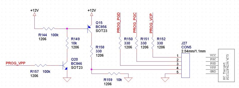
I add 330 Ohms to prevent short-circuit. And a pull down on VPP (R159) to ensure the return of the target in standby mode.
Any comment, post it  . .
@+ Stephanfo |
|
|
Storic
Joined: 03 Dec 2005
Posts: 182
Location: Australia SA

|
|
| Posted: Thu Jun 01, 2006 4:21 pm |
|
|
I will try your code at some time, as programming a pic from a pic is what I ha been looking for, I was thinking about a bootloader however your methode may be better, (After I program the micro, I wanted to use the RX/TX for communication between the micros for data functions.
(I will be tring the 18F1320 or the 16F87 to be program by a dsPIC or 24F)
ANdrew
_________________
What has been learnt if you make the same mistake? |
|
|
ratgod
Joined: 27 Jan 2006
Posts: 69
Location: Manchester, England
|
|
| Posted: Mon Sep 17, 2007 8:59 pm |
|
|
do you know how to use this to program chips such as PIC18F2520, 2550 and 2580? or maybe the PIC16F877A?
many thanks |
|
|
nuno12345
Joined: 16 Jul 2008
Posts: 50
|
|
| Posted: Thu Jun 25, 2009 11:19 am |
|
|
Hello, old thread but as anyone tested this?
Do we really need BC856/BC846 or can we use BC556/BC546? |
|
|
Ln_mark7930
Joined: 06 Mar 2009
Posts: 21
|
| Where find PIC info? |
| Posted: Tue Nov 03, 2009 10:53 am |
|
|
Where Can I find Information about:
ISPROG_OSCCAL_ADDRESS
ISPROG_CONFIG_ADDRESS
ISPROG_CONFIG_UTIL_MASK
ISPROG_CONFIG_SAVE_MASK ???
Inside datasheet of microchip there are not information about this data.
I test the code with one 12F629 and its work perfectly, but if I try to recompile the code to trasfert it inside a 12F683 it doesn't work because register are wrong.
Someone can help me? |
|
|
PCM programmer
Joined: 06 Sep 2003
Posts: 21708
|
|
| Posted: Tue Nov 03, 2009 1:06 pm |
|
|
| Quote: |
Where can I find information about:
ISPROG_OSCCAL_ADDRESS
|
Look in this section of the 12F629 data sheet. It's given in the sample code:
| Quote: | EXAMPLE 9-1: CALIBRATING THE
INTERNAL OSCILLATOR
|
| Quote: |
Where can I find information about:
ISPROG_CONFIG_ADDRESS
|
Look in the title of this section (at the lsb):
| Quote: |
REGISTER 9-1: CONFIG — CONFIGURATION WORD (ADDRESS: 2007h) |
| Quote: |
Where can I find information about:
ISPROG_CONFIG_UTIL_MASK
|
Look at the bit diagram of the Config Word in this section. Notice that
it has 9 contiguous bits on the right side of the word. The bitmask for
these bits (in hex) is 0x1FF.
| Quote: |
REGISTER 9-1: CONFIG — CONFIGURATION WORD (ADDRESS: 2007h)
|
| Quote: |
Where can I find information about:
ISPROG_CONFIG_SAVE_MASK
|
Again, look at the Config Word in this section. The two "Bandgap" bits
on the left of the bit diagram are determined by the Microchip factory
during chip testing. You don't want to change those bits. You want
to save them from changes. The bitmask for those bits is 0x3000.
| Quote: |
REGISTER 9-1: CONFIG — CONFIGURATION WORD (ADDRESS: 2007h)
|
For more information, look in the Programming Specification for the
12F629:
http://ww1.microchip.com/downloads/en/DeviceDoc/41191D.pdf
It also gives the addresses for the OSCCAL byte, the data eeprom
address, and the Device ID values (you can see the bitmask for the
Device ID by looking at the bit range). |
|
|
Ln_mark7930
Joined: 06 Mar 2009
Posts: 21
|
| I need help with 18f2520 |
| Posted: Fri Jun 11, 2010 6:50 am |
|
|
Hi boys,
I need to edit the original firmware from 12f629 to 18f2520.
I see the 18f2xxx Programming Specification and I see that the program mode is different.
Have someone the final code for PIC18f2520 or similar???
Thanks at all.
Mark |
|
|
|
|
You cannot post new topics in this forum
You cannot reply to topics in this forum
You cannot edit your posts in this forum
You cannot delete your posts in this forum
You cannot vote in polls in this forum
|
Powered by phpBB © 2001, 2005 phpBB Group
|

