 |
 |
| View previous topic :: View next topic |
| Author |
Message |
ulg
Joined: 09 May 2019
Posts: 24


|
| ADC / DMA / dsPIC33FJ128MC706 |
 Posted: Mon Sep 02, 2019 1:37 am Posted: Mon Sep 02, 2019 1:37 am |
 |
|
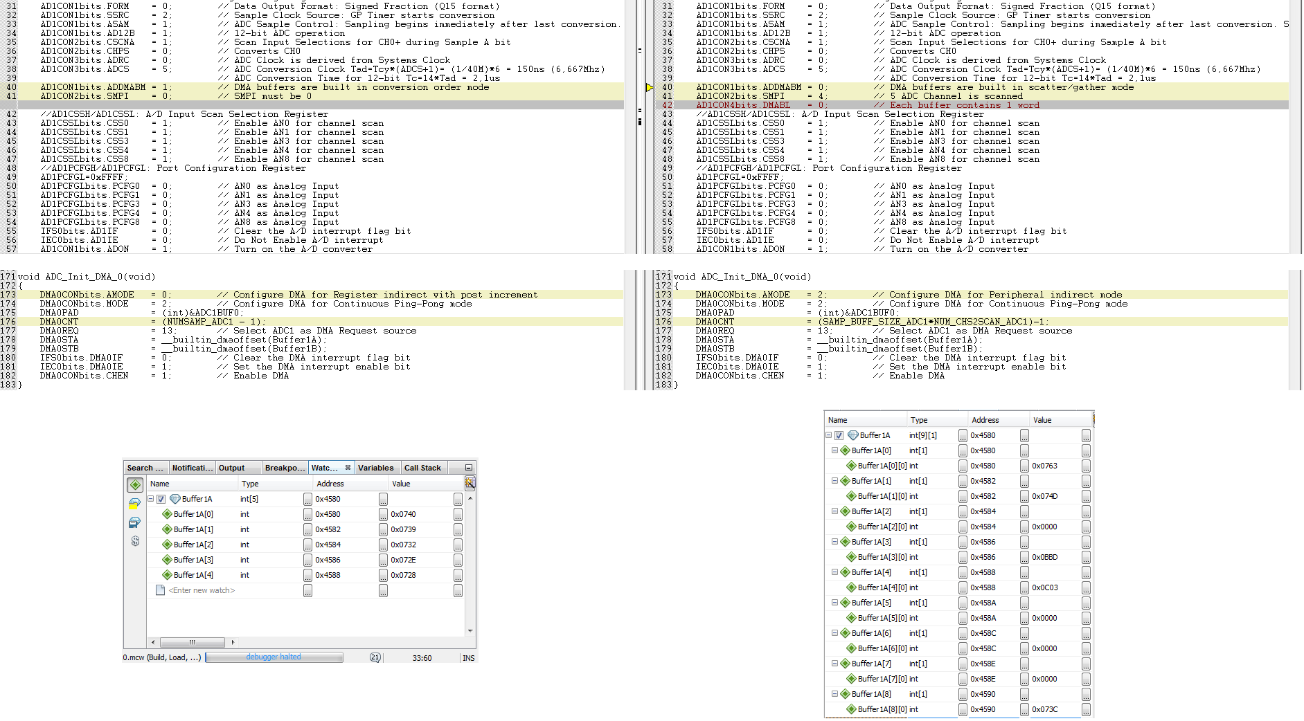
On an existing application the ADC sampling of five channels is done
in "scatter / gather mode" with 50KHz. The associated
DMA interrupt routine eats 50% of processor time!
I want to modify the application - in the end I want convert the five
AD channels in "conversion order mode" eight times before the DMA
interrupt routine will process them with 6.25KHz.
In a first step, I wanted want to convert the five AD channels once
in "conversion order mode", before they are processed in the
DMA interrupt routine still with 50kHz, but not even that works.
It seems, that the same AD channel is converted five times (picture left
"conversion order mode", right picture "scatter / gather mode").
Does anyone have a tip, what I'm doing wrong (on the internet I can
find only "conversion order mode" examples converting a single channel
several times) ? Or do I understand the datasheet wrong and
the controller doesn't support converting multiple AD channels in
"conversion order mode"?
 |
|
 |
Ttelmah
Joined: 11 Mar 2010
Posts: 20066
|
|
| Posted: Mon Sep 02, 2019 2:10 am |
|
|
It's not clear from what you post, where you are telling the DMA to fetch
the value 'from'?. I found this was what caused issues. You have to set the
DMA to fetch it's results from the register ADC1RESDMA to get the correct
figures. It is this register that sequentially is loaded with the ADC results.
So:
| Code: |
#word DMAADC=getenv("SFR:AD1RESDMA")
//and for 'one shot', rather than ping_pong, using 132 byte buffer
setup_dma(0, DMA_TRIGGER_ADC1, DMA_WORD); // | DMA_RELOAD_ADDRESS);
dma_start(0, DMA_ONE_SHOT | DMA_INC_DEST_ADDR , DMA_BUFFER , &DMAADC, 132); //2*34
|
You seem not to be using the CCS DMA functions?.
In fact looking at what you have posted, the register names you are
using are the MicroChip values. You do realise this is a forum for CCS C,
not a generic 'PIC' forum?. If you are using MicroChip C, you need to be
asking your question on the MicroChip forum, not here. |
|
|
ulg
Joined: 09 May 2019
Posts: 24
|
|
| Posted: Mon Sep 02, 2019 4:55 am |
|
|
The value 'from' is configured in line 175:
DMA0PAD = (int)&ADC1BUF0;
Because I have to work with both, CCS & Microchip C, I wasn't aware. that
I have translated my problem from German to English for a CCS forum - sorry.
When I relized this, I have had the hope, I will get hints to solve it also
from people ready to help in a CCS forum, as the problem seems to be a
hardware specific, not a Microchip C specific (right side with "scatter/gather
mode" will work). |
|
|
Ttelmah
Joined: 11 Mar 2010
Posts: 20066
|
|
| Posted: Mon Sep 02, 2019 5:02 am |
|
|
My answer applies to the problem. ADCBUF1, is _not_ the right register.
You have to use the ADC1RESDMA register. Otherwise you won't get
the correct increment of the channel.
It is not well explained in the chip data sheet. It looks as if you should use
the ADC buffer, but you don't.... |
|
|
ulg
Joined: 09 May 2019
Posts: 24
|
|
| Posted: Mon Sep 02, 2019 5:22 am |
|
|
I'm confused, because whether MPLAB nor the datasheet know about ADC1RESDMA (or ADC1RES*) !?
In the datasheet I found:
"3. On devices with a DMA module, the ADC
module has only 1 ADC result buffer, (i.e.,
ADC1BUF0), per ADC peripheral and the ADC
conversion result must be read either by the
CPU or DMA controller before the next ADC
conversion is complete to avoid overwriting the
previous value." |
|
|
Ttelmah
Joined: 11 Mar 2010
Posts: 20066
|
|
| Posted: Mon Sep 02, 2019 6:34 am |
|
|
Being 'hardware specific', makes it even less applicable to this forum.
As I said, 'this is a forum for issues with CCS C'. Not a generic 'PIC' forum.
Now the AD1RESDMA solution, was one I was given by MicroChip, when I
was having an issue on another chip with DMA, where it continuously
returned the value from the first analog channel, and they said to access
this register for DMA, not the buffer register (though the data sheet said
to access the buffer register). Probably does not apply to your chip.
You do not seem to be setting the ALTS, or BUFM bits in the ADC
configuration. These affect the order the values are allocated to the
buffer.
You also have to increment the address whichever mode you are using.
Otherwise you are always only reading the result from the first channel.
If you want ot access AN0 to AN8 without using scatter/gather, you would
need to use 9 readings. With scatter/gather, just 5. |
|
|
ulg
Joined: 09 May 2019
Posts: 24
|
|
| Posted: Mon Sep 02, 2019 9:31 am |
|
|
As I understood the datasheet, I can fill with "conversion order mode" a one dimensional DMA buffer with the first sample sequence of the five channels, I have enabled to scan, then the second sample sequence, the third, the fourth, ...
| Code: |
Name type Value
Buffer1A int[40]
Buffer1A[0] int AN0_Sample0
Buffer1A[1] int AN1_Sample0
Buffer1A[2] int AN3_Sample0
Buffer1A[3] int AN4_Sample0
Buffer1A[4] int AN8_Sample0
Buffer1A[5] int AN0_Sample1
Buffer1A[6] int AN1_Sample1
Buffer1A[7] int AN3_Sample1
Buffer1A[8] int AN4_Sample1
Buffer1A[9] int AN8_Sample1
Buffer1A[10] int AN0_Sample2
Buffer1A[11] int AN1_Sample2
Buffer1A[12] int AN3_Sample2
Buffer1A[13] int AN4_Sample2
Buffer1A[14] int AN8_Sample2
Buffer1A[15] int AN0_Sample3
Buffer1A[16] int AN1_Sample3
Buffer1A[17] int AN3_Sample3
Buffer1A[18] int AN4_Sample3
Buffer1A[19] int AN8_Sample3
Buffer1A[20] int AN0_Sample4
Buffer1A[21] int AN1_Sample4
Buffer1A[22] int AN3_Sample4
Buffer1A[23] int AN4_Sample4
Buffer1A[24] int AN8_Sample4
Buffer1A[25] int AN0_Sample5
Buffer1A[26] int AN1_Sample5
Buffer1A[27] int AN3_Sample5
Buffer1A[28] int AN4_Sample5
Buffer1A[29] int AN8_Sample5
Buffer1A[30] int AN0_Sample6
Buffer1A[31] int AN1_Sample6
Buffer1A[32] int AN3_Sample6
Buffer1A[33] int AN4_Sample6
Buffer1A[34] int AN8_Sample6
Buffer1A[35] int AN0_Sample7
Buffer1A[36] int AN1_Sample7
Buffer1A[37] int AN3_Sample7
Buffer1A[38] int AN4_Sample7
Buffer1A[39] int AN8_Sample7
|
Maybe I have misinterpreted the datasheet!? |
|
|
Ttelmah
Joined: 11 Mar 2010
Posts: 20066
|
|
| Posted: Mon Sep 02, 2019 10:46 am |
|
|
If build mode is set to 1, the results in the buffer are built in channel
order, not the enabled order. So you will have big gaps in the data. So with
your example, you will get AN0, AN1, gap, AN3, AN4, gap, gap gap, AN8.
and you will need to take 9 readings, to get a complete 'set'.
You will need to configure 9 readings for each loop, or the counter
resets to the first channel. |
|
|
ulg
Joined: 09 May 2019
Posts: 24
|
|
| Posted: Wed Sep 04, 2019 12:14 am |
|
|
Problem solved!
Under "Register 16-2: ADxCON2: ADCx Control Register 2" one can find:
| Code: |
bit 5-2 SMPI<3:0>: Sample and Conversion Operation bits (1,2)
For devices with DMA:
1111 = Increments the DMA address after completion of every 16th sample/conversion operation
1110 = Increments the DMA address after completion of every 15th sample/conversion operation
.
.
.
0001 = Increments the DMA address after completion of every 2nd sample/conversion operation
0000 = Increments the DMA address after completion of every sample/conversion operation
|
Consistent with this seems to be, what one can find in Microchip's examples with "conversion order mode" - "SMPI must be 0" - as you would like, that the next conversion result will be stored one int16 behind the last one..
| Code: |
AD1CON2bits.SMPI = 0; // SMPI must be 0
|
That's wrong - SMPI must be set equal to the number of inputs to scan minus 1!
| Code: |
AD1CON2bits.SMPI = NumberOfInputsToScan - 1;
|
Because under "16.4.6.2 SMPI FOR DEVICES WITH DMA" one can find:
| Code: |
When channel scanning is used (and Alternate Input Selection mode is disabled), the SMPI<3:0>
bits should be set to the number of inputs being scanned minus one (i.e., SMPI<3:0> = N - 1).
|
Now all five channels will be scanned.
https://www.mikrocontroller.net/attachment/427929/ADC1values1Dgood.png
In addition, if the DMA is programmed to collect the results of eight such scan sequences, one obtains a DMA interrupt after every 40 conversions, which then occur at an interrupt frequency of 6.25 kHz.
https://www.mikrocontroller.net/attachment/427930/ADC1values1D40_1.png
Thx for your willingness to help. |
|
|
Ttelmah
Joined: 11 Mar 2010
Posts: 20066
|
|
| Posted: Wed Sep 04, 2019 7:23 am |
|
|
As I said.
Yes, the SMPI setting is awfully documented, but if you look at their
own examples, you will see they set it to handle the number of channels
that have to be sampled. The key is that when this triggers, it sets the
internal counter used to handle the offsets used for the channels back to 0.
So with it set to zero, you only ever sample the first channel.... |
|
|
|
|
You cannot post new topics in this forum
You cannot reply to topics in this forum
You cannot edit your posts in this forum
You cannot delete your posts in this forum
You cannot vote in polls in this forum
|
Powered by phpBB © 2001, 2005 phpBB Group
|

