 |
 |
| View previous topic :: View next topic |
| Author |
Message |
pizdec
Joined: 21 Sep 2018
Posts: 6


|
| [SOLVED]PIC18F4550 + HC-05 module receiving wrong characters |
 Posted: Fri Sep 21, 2018 2:56 am Posted: Fri Sep 21, 2018 2:56 am |
 |
|
Hi, I'm trying to make a bluetooth communication with a PIC18F4550 through a HC-05 module. Characters are displayed through a LCD 2x16 display.
I've tried with my PC (microsoft store apps), with mobile phone, even I made my own app through visual C# and i'm getting the same issue sending characters to my PIC18F4550.
The display works fine and the HC-05 module is well linked to my PC (windows 10), i'm receiving a character everything I send something from my PC/Phone but it receives the wrong character.
My code:
| Code: |
#include <18F4550.h>
#fuses XT,NOWDT,NOMCLR,NOLVP,NOBROWNOUT,NOPROTECT
#use delay(clock=4M)
#use rs232(BAUD=9600, XMIT= PIN_C6, RCV= PIN_C7, PARITY=N, BITS=8, STOP=1)
#include <string.h>
#include <lcd.c>
#define LCD_ENABLE_PIN PIN_D0
#define LCD_RS_PIN PIN_D1
#define LCD_RW_PIN PIN_D2
#define LCD_DATA4 PIN_D4
#define LCD_DATA5 PIN_D5
#define LCD_DATA6 PIN_D6
#define LCD_DATA7 PIN_D7
void main ()
{
lcd_init();
while(true)
{
if (kbhit())
{
char c = getc();
printf(lcd_putc,"\f%c",c);
}
}
}
|
I'm using a 4Mhz crystal with two 22pF capacitors
I've tried sending characters from my PIC to my PC and it also sends the wrong characters.
Any ideas?
How I solved it
1) Add the #fuse CPUDIV1, it solved the disorder in the bits (Ttelmah was right)
2) No I2C logic level converter used for it, I connected the HC-05 module direct to the PIC18F4550 pins.
3) I was receiving extra characters after the first char I sent
E.g: When I send an 'a', I was receiving: 'a\r', so the LCD never shown the char I was receiving first.
Even when I sent directly a char without an inferfaced software (to avoid send an ENTER to the PIC)
To check it, I resend the received chars plus the ascii code back to the PC to check what was I receiving (due to the LCD couldn't show me the extra lines)


My #fuses and other configs
| Code: | #include <18F4550.h>
#use delay(clock=4M)
#use fast_io(D)
#fuses HS,NOWDT,NOPROTECT,NOLVP,MCLR,CPUDIV1
#use RS232(BAUD=9600, XMIT=PIN_C6, RCV=PIN_C7, BITS=8, STREAM=salida, PARITY=N) |
Thank you Ttelmah and temtronic.
Last edited by pizdec on Tue Oct 02, 2018 4:06 am; edited 2 times in total |
|
 |
Ttelmah
Joined: 11 Mar 2010
Posts: 20079
|
|
| Posted: Fri Sep 21, 2018 3:05 am |
|
|
Yes.
You need a buffer chip between the HC05 and the PIC, or to switch to a 3.3v PIC.
The PIC serial input _requires_ signals to go to 0.8*Vdd to be seen as a '1'. For a 5v PIC, 4v. The HC05 has a maximum output voltage, just a little under 3v... |
|
|
temtronic
Joined: 01 Jul 2010
Posts: 9641
Location: Greensville,Ontario
|
|
| Posted: Fri Sep 21, 2018 4:45 am |
|
|
The alternate option is to use a 3 volt PIC. One that says xxLFyyyy. The L means it is designed to operate on 3 volts. There are some PICs (like the 18F46K22) that do operate at 3 or 5 volts, so you need to carefully look at the datasheets. There's always a chart that shows operation speed vs VDD.
Another option, you may find an HC-05 module that has built in 'logic level conversion' that Mr. T speaks of, probably rare though.
I see many places sell those 'conversion' PCBs in duals, quads and octal configurations usually for $1 or 2.
edit...
did a quick search...
https://www.banggood.com/search/logic-level-converter-module/0-0-0-1-3-44-0-price-0-0_p-1.html?sbc=1&sortType=asc
..really hard to hand solder 2Rs and a FET when you can buy an octal board for a bit over a buck.... my eyes are aging and hate hitting my fingers with hot solder these days... 
Last edited by temtronic on Fri Sep 21, 2018 7:22 am; edited 1 time in total |
|
|
newguy
Joined: 24 Jun 2004
Posts: 1936
|
|
|
pizdec
Joined: 21 Sep 2018
Posts: 6
|
|
| Posted: Fri Sep 21, 2018 12:08 pm |
|
|
| Ttelmah wrote: | Yes.
You need a buffer chip between the HC05 and the PIC, or to switch to a 3.3v PIC.
The PIC serial input _requires_ signals to go to 0.8*Vdd to be seen as a '1'. For a 5v PIC, 4v. The HC05 has a maximum output voltage, just a little under 3v... |
How about send data from the PIC to HC-05? It also sends the wrong characters. |
|
|
temtronic
Joined: 01 Jul 2010
Posts: 9641
Location: Greensville,Ontario
|
|
| Posted: Fri Sep 21, 2018 12:20 pm |
|
|
Similar problem.. the PIC is overdriving the HC05.
You MUST have proper logic levels for it to work and without them you could damage the HC05 unit. HC05 tends to be a 'generic' name for a variety of wireless 'modules' and without knowing specifically which you're using we can't say what the damage will be.
You NEED to spend $1 and get 'logic level conversion ' module or make your own. Until then you will get 'garbage'.
You MUST apply a hardware fix, software will not fix the problem.
Jay |
|
|
Ttelmah
Joined: 11 Mar 2010
Posts: 20079
|
|
| Posted: Fri Sep 21, 2018 12:40 pm |
|
|
A lot of the modules sold for use with the Arduino, already have a resistor divider built in to handle 5v 'out' (since the Arduino also generates this), but do not have the buffer to handle the input (since the Arduino only requires 2.4v for it's logic inputs). If it is sending the wrong characters though, it sounds as if this one doesn't have this.
There is another issue though:
| Code: |
#fuses XT,NOWDT,NOMCLR,NOLVP,NOBROWNOUT,NOPROTECT,CPUDIV1
|
This fuse needs to be added or it is never going to work right. |
|
|
pizdec
Joined: 21 Sep 2018
Posts: 6
|
|
| Posted: Tue Sep 25, 2018 1:54 pm |
|
|
| Ttelmah wrote: | Yes.
You need a buffer chip between the HC05 and the PIC, or to switch to a 3.3v PIC.
The PIC serial input _requires_ signals to go to 0.8*Vdd to be seen as a '1'. For a 5v PIC, 4v. The HC05 has a maximum output voltage, just a little under 3v... |
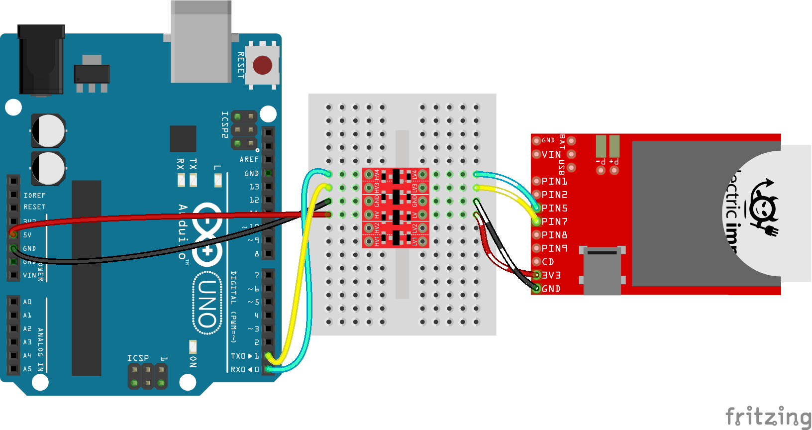
I bought a PIC16F877A and tested it on the same circuit, it worked well.
But I also bought the I2C logic Lever Converter thing and tested with the PIC18F4550 and still not working, here's the circuit:
It prints on the LCD, the character and the value on the ASCII code:
| Code: | | printf(lcd_putc,"\f %c(%i), c, (int) c"); |
I sent the character 'a' and I get this:

It's not lineal, I mean, some characters give me the same result. |
|
|
temtronic
Joined: 01 Jul 2010
Posts: 9641
Location: Greensville,Ontario
|
|
| Posted: Tue Sep 25, 2018 4:04 pm |
|
|
If you can, post a schematic or just describe in text, as I'm curious as to what the 8 pin DIP chip is doing.
Wireless communications does require proper physical and electrical conditions. Missed or bad charaters could be loss of signal (something like a hand) partially blocking the transmission or lack of power. Most wireless devices need a lot of power for transmitting, so a good, solid 2 amp rated supply will be needed. Often the VDD to the device will also need say a 1000mfd cap to help 'smooth' and maintain the 5 or 3 volts during transmission.
Jay |
|
|
pizdec
Joined: 21 Sep 2018
Posts: 6
|
|
| Posted: Tue Sep 25, 2018 10:27 pm |
|
|
| temtronic wrote: | If you can, post a schematic or just describe in text, as I'm curious as to what the 8 pin DIP chip is doing.
Wireless communications does require proper physical and electrical conditions. Missed or bad charaters could be loss of signal (something like a hand) partially blocking the transmission or lack of power. Most wireless devices need a lot of power for transmitting, so a good, solid 2 amp rated supply will be needed. Often the VDD to the device will also need say a 1000mfd cap to help 'smooth' and maintain the 5 or 3 volts during transmission.
Jay |
It's a LM358, since the IC2 logic level converter requires a Low Voltage input, I made a voltage divider to get near of 3.3V from 5V source, so I used the LM358 to make a voltage follower.
My circuit made in paint :P
 |
|
|
Ttelmah
Joined: 11 Mar 2010
Posts: 20079
|
|
| Posted: Tue Sep 25, 2018 11:25 pm |
|
|
Have you fixed the CPUDIV fuse?. Otherwise the chip will not be running at the speed you expect, so serial will not work.
Also does your voltage shifter module need pull-ups?. Some do. The HC05 should have it's own, but you have none between the shifter and the PIC. |
|
|
pizdec
Joined: 21 Sep 2018
Posts: 6
|
|
| Posted: Wed Sep 26, 2018 1:42 am |
|
|
| Ttelmah wrote: | Have you fixed the CPUDIV fuse?. Otherwise the chip will not be running at the speed you expect, so serial will not work.
Also does your voltage shifter module need pull-ups?. Some do. The HC05 should have it's own, but you have none between the shifter and the PIC. |
When I add the CPUDIV fuse, it looks worse, it doesn't even receive any character.
In other hand, with the PIC16F877A it works perfetcly without that fuse, it worked in the same circuit and code (just by changing the pic's library)
As far I know, the usage is something like this:
 |
|
|
Ttelmah
Joined: 11 Mar 2010
Posts: 20079
|
|
| Posted: Wed Sep 26, 2018 2:26 am |
|
|
You can't use the the approach that "this chip doesn't need a fuse, so this other one won't". The chips are fundamentally different in their clock structures.
The 877A has just 11 fuse bits. The 4550 has over 50....
The 4550, is designed to support USB. To help meet the clock requirements to do this it has two separate 'routes' that the clock can be sent from the crystal to the actual CPU.
The first goes via a programmable divider offering /1, /2, /3 & /4 from the incoming clock. This defaults to giving /4.
The second route goes via a divider offering /1, /2, /3, /4, /5, /6, /10 & /12, which then feeds to a PLL giving *24, and then to another divider giving /2, /3, /4 & /6.
With XT selected you should be going via the first route, but the divider will be giving /4, so your chip will only be running at 1MHz.
If I compile your code, this is what the fuses give:
| Code: |
Configuration Fuses:
Word 1: C03F PLL12 CPUDIV4 USBDIV XT FCMEN IESO
Word 2: 1E38 PUT NOBROWNOUT BORV21 VREGEN NOWDT WDT32768
Word 3: 0700 CCP2C1 PBADEN LPT1OSC NOMCLR
Word 4: 00A1 STVREN NOLVP ICSP2 NOXINST NODEBUG
Word 5: C00F NOPROTECT NOCPB NOCPD
Word 6: E00F NOWRT NOWRTC NOWRTB NOWRTD
Word 7: 400F NOEBTR NOEBTRB
|
Note the CPUDIV4 fuse....
You _need_ the CPUDIV1 fuse. |
|
|
temtronic
Joined: 01 Jul 2010
Posts: 9641
Location: Greensville,Ontario
|
|
| Posted: Wed Sep 26, 2018 5:00 am |
|
|
Just to followup on MR. T's comments... when I used the 4550 years ago, I would printout the 'Figure 2-1 clock diagram' from the 4550 datasheet. I then used a 'highlighter' pen to show myself how the clock was going to be created. There's a LOT of options and it's easy to get confused, I know I did !!
Something you should do is code/comple/test a '1Hz LED program' Simply add an LED and 470r to an unused I/O pin. Cut simple code to toggle the LED at a 1Hz rate.compile and run. If it's not close to 1Hz you KNOW you've got a clock configuration problem (aka wrong fuse). When you get the LED flashing properly, then go to your original program and edit those fuses to be the same as the working 1Hz LED program.
Jay |
|
|
Ttelmah
Joined: 11 Mar 2010
Posts: 20079
|
|
| Posted: Wed Sep 26, 2018 12:38 pm |
|
|
As a further comment, the HC05, should not work with the 16F877A either,
unless you are either using the LF version of the PIC and running it at 3.3v,
or are using software RS232, rather than the hardware port (the software
serial has TTL input thresholds, rather than Schmitt thresholds).
The HC05, is based on the BlueCore4 chipset, and this does not produce
enough output voltage to drive the PIC hardware UART input pins on a 5v
PIC.
Have you got any test instruments at all?.
If you have a scope, you need to be looking at the waveforms. Does the
serial input to the PIC go up to at least 4v. It isn't going to work unless it
does. |
|
|
|
|
You cannot post new topics in this forum
You cannot reply to topics in this forum
You cannot edit your posts in this forum
You cannot delete your posts in this forum
You cannot vote in polls in this forum
|
Powered by phpBB © 2001, 2005 phpBB Group
|

