 |
 |
| View previous topic :: View next topic |
| Author |
Message |
champ720
Joined: 22 Dec 2010
Posts: 12


|
| PIC16F877A and LCD 16x2 problem |
 Posted: Fri Jan 21, 2011 5:31 am Posted: Fri Jan 21, 2011 5:31 am |
 |
|
Hello, I'm testing my LCD 16x2 (ABC016002A07-GHY) with PIC16F877A and flex_led.c driver but it's not work (appear black square in first line). I try these method below but it's not work.
1. Increase the initial delay to a much larger value, such as 50 ms.
2. Check the +5v power supply. Make sure it stays at a constant +5v.
3. If those two things don't help, then configure the LCD and driver
for Write-only mode. Instructions:
A. Break the connection between the LCD_RW pin and pin A2 on
the PIC.
B. Connect the LCD_RW pin to ground.
C. Don't connect anything to pin A2 on the PIC.
D. In the Flex_lcd.c driver, comment out #define statement for
USE_RW_PIN. Example:
Code:
// #define USE_RW_PIN 1
E. Re-compile the program.
F. Re-program the PIC and test it.
This is LCD datasheet :
http://www.mediafire.com/?io9zpabz4itz6ao
This is define word :
// flex_lcd.c
// These pins are for the Microchip PicDem2-Plus board,
// which is what I used to test the driver. Change these
// pins to fit your own board.
#define LCD_DB4 PIN_D4
#define LCD_DB5 PIN_D5
#define LCD_DB6 PIN_D6
#define LCD_DB7 PIN_D7
#define LCD_E PIN_D0
#define LCD_RS PIN_D1
#define LCD_RW PIN_D2
// If you only want a 6-pin interface to your LCD, then
// connect the R/W pin on the LCD to ground, and comment
// out the following line.
//#define USE_LCD_RW 1
//========================================
#define lcd_type 2 // 0=5x7, 1=5x10, 2=2 lines
#define lcd_line_two 0x40 // LCD RAM address for the 2nd line
-------------------------------------------------------------------------------------
This is the main program that I compile :
#include <16F877A.h> // Standard Header file for the PIC16F877A
#fuses HS,NOWDT,NOPROTECT,NOLVP,PUT,BROWNOUT // Configuration word
#use delay(clock=20000000) // oscillator
#include "flex_led.c"
//----------------------------------------------------------//
void main(void)
{
lcd_init();
while(TRUE)
{
// LCD Display //
lcd_putc("\f"); //Clear display
lcd_gotoxy(1,1);
lcd_putc("Champ");
delay_ms(1000);
}
}
please help me, thank you. |
|
 |
champ720
Joined: 22 Dec 2010
Posts: 12
|
|
| Posted: Fri Jan 21, 2011 6:16 am |
|
|
| I compile with PCWHD 4.068 |
|
|
demonspells
Joined: 06 Jan 2011
Posts: 26


|
|
| Posted: Fri Jan 21, 2011 7:44 am |
|
|
| Quote: | | C. Don't connect anything to pin A2 on the PIC. |
I think you meant pin D2. right?
did you try the default <lcd.c> routine? is it working?
your code looks fine, try re-checking your connections |
|
|
gpsmikey
Joined: 16 Nov 2010
Posts: 588
Location: Kirkland, WA
|
|
| Posted: Fri Jan 21, 2011 7:47 am |
|
|
In addition to the comment above on D2, make sure you have power and ground to the display correctly (favorite trick is to hook up data/control lines and forget power and ground ... very odd things happen that way).
mikey
_________________
mikey
-- you can't have too many gadgets or too much disk space !
old engineering saying: 1+1 = 3 for sufficiently large values of 1 or small values of 3 |
|
|
champ720
Joined: 22 Dec 2010
Posts: 12
|
|
| Posted: Fri Jan 21, 2011 10:08 pm |
|
|
| demonspells wrote: | | Quote: | | C. Don't connect anything to pin A2 on the PIC. |
I think you meant pin D2. right?
did you try the default <lcd.c> routine? is it working?
your code looks fine, try re-checking your connections |
Yes, I connect RW at D2. I change driver to LCD.c but not work. |
|
|
champ720
Joined: 22 Dec 2010
Posts: 12
|
|
| Posted: Fri Jan 21, 2011 10:41 pm |
|
|
| gpsmikey wrote: | In addition to the comment above on D2, make sure you have power and ground to the display correctly (favorite trick is to hook up data/control lines and forget power and ground ... very odd things happen that way).
mikey |
connection of power and ground is correct
| Code: |
LCD
PIN 1 --> Ground
PIN 2 --> +5V
PIN 3 --> POT 20K
PIN 4 - RS --> RD1
PIN 5 - R/W --> RD2
PIN 6 - E --> RD0
PIN 7 --> GND
PIN 8 --> GND
PIN 9 --> GND
PIN 10 --> GND
PIN 11 --> RD4
PIN 12 --> RD5
PIN 13 --> RD6
PIN 14 --> RD7
PIN 15 --> +5V
PIN 16 --> GND |
This is flex_led.c that I compile :
| Code: |
// flex_lcd.c
// These pins are for the Microchip PicDem2-Plus board,
// which is what I used to test the driver. Change these
// pins to fit your own board.
#define LCD_DB4 PIN_D4
#define LCD_DB5 PIN_D5
#define LCD_DB6 PIN_D6
#define LCD_DB7 PIN_D7
#define LCD_E PIN_D0
#define LCD_RS PIN_D1
#define LCD_RW PIN_D2
// If you only want a 6-pin interface to your LCD, then
// connect the R/W pin on the LCD to ground, and comment
// out the following line.
//#define USE_LCD_RW 1
//========================================
#define lcd_type 2 // 0=5x7, 1=5x10, 2=2 lines
#define lcd_line_two 0x40 // LCD RAM address for the 2nd line
int8 const LCD_INIT_STRING[4] =
{
0x20 | (lcd_type << 2), // Func set: 4-bit, 2 lines, 5x8 dots
0xc, // Display on
1, // Clear display
6 // Increment cursor
};
//-------------------------------------
void lcd_send_nibble(int8 nibble)
{
// Note: !! converts an integer expression
// to a boolean (1 or 0).
output_bit(LCD_DB4, !!(nibble & 1));
output_bit(LCD_DB5, !!(nibble & 2));
output_bit(LCD_DB6, !!(nibble & 4));
output_bit(LCD_DB7, !!(nibble & 8));
delay_cycles(1);
output_high(LCD_E);
delay_us(2);
output_low(LCD_E);
}
//-----------------------------------
// This sub-routine is only called by lcd_read_byte().
// It's not a stand-alone routine. For example, the
// R/W signal is set high by lcd_read_byte() before
// this routine is called.
#ifdef USE_LCD_RW
int8 lcd_read_nibble(void)
{
int8 retval;
// Create bit variables so that we can easily set
// individual bits in the retval variable.
#bit retval_0 = retval.0
#bit retval_1 = retval.1
#bit retval_2 = retval.2
#bit retval_3 = retval.3
retval = 0;
output_high(LCD_E);
delay_cycles(1);
retval_0 = input(LCD_DB4);
retval_1 = input(LCD_DB5);
retval_2 = input(LCD_DB6);
retval_3 = input(LCD_DB7);
output_low(LCD_E);
return(retval);
}
#endif
//---------------------------------------
// Read a byte from the LCD and return it.
#ifdef USE_LCD_RW
int8 lcd_read_byte(void)
{
int8 low;
int8 high;
output_high(LCD_RW);
delay_cycles(1);
high = lcd_read_nibble();
low = lcd_read_nibble();
return( (high<<4) | low);
}
#endif
//----------------------------------------
// Send a byte to the LCD.
void lcd_send_byte(int8 address, int8 n)
{
output_low(LCD_RS);
#ifdef USE_LCD_RW
while(bit_test(lcd_read_byte(),7)) ;
#else
delay_us(60);
#endif
if(address)
output_high(LCD_RS);
else
output_low(LCD_RS);
delay_cycles(1);
#ifdef USE_LCD_RW
output_low(LCD_RW);
delay_cycles(1);
#endif
output_low(LCD_E);
lcd_send_nibble(n >> 4);
lcd_send_nibble(n & 0xf);
}
//----------------------------
void lcd_init(void)
{
int8 i;
output_low(LCD_RS);
#ifdef USE_LCD_RW
output_low(LCD_RW);
#endif
output_low(LCD_E);
delay_ms(15);
for(i=0 ;i < 3; i++)
{
lcd_send_nibble(0x03);
delay_ms(5);
}
lcd_send_nibble(0x02);
for(i=0; i < sizeof(LCD_INIT_STRING); i++)
{
lcd_send_byte(0, LCD_INIT_STRING[i]);
// If the R/W signal is not used, then
// the busy bit can't be polled. One of
// the init commands takes longer than
// the hard-coded delay of 60 us, so in
// that case, lets just do a 5 ms delay
// after all four of them.
#ifndef USE_LCD_RW
delay_ms(5);
#endif
}
}
//----------------------------
void lcd_gotoxy(int8 x, int8 y)
{
int8 address;
if(y != 1)
address = lcd_line_two;
else
address=0;
address += x-1;
lcd_send_byte(0, 0x80 | address);
}
//-----------------------------
void lcd_putc(char c)
{
switch(c)
{
case '\f':
lcd_send_byte(0,1);
delay_ms(2);
break;
case '\n':
lcd_gotoxy(1,2);
break;
case '\b':
lcd_send_byte(0,0x10);
break;
default:
lcd_send_byte(1,c);
break;
}
}
//------------------------------
#ifdef USE_LCD_RW
char lcd_getc(int8 x, int8 y)
{
char value;
lcd_gotoxy(x,y);
// Wait until busy flag is low.
while(bit_test(lcd_read_byte(),7));
output_high(LCD_RS);
value = lcd_read_byte();
output_low(lcd_RS);
return(value);
}
#endif |
|
|
|
gpsmikey
Joined: 16 Nov 2010
Posts: 588
Location: Kirkland, WA
|
|
| Posted: Fri Jan 21, 2011 10:57 pm |
|
|
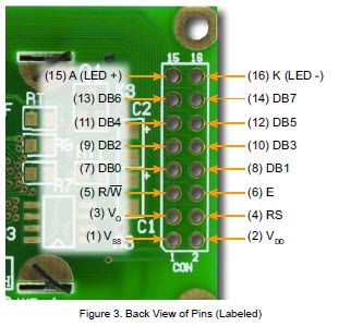
That is basically the way I have my LCD (CrystalFontz in this case) connected although D0-D3 are not connected. Just out of curiosity, how did you count the pin numbers on the connector ? They alternate back and forth, not down one side and up the other like an IC. See the connector pin-out of mine - I expect yours uses the same connector ?
mikey
_________________
mikey
-- you can't have too many gadgets or too much disk space !
old engineering saying: 1+1 = 3 for sufficiently large values of 1 or small values of 3 |
|
|
champ720
Joined: 22 Dec 2010
Posts: 12
|
|
| Posted: Sat Jan 22, 2011 12:04 am |
|
|
| gpsmikey wrote: | That is basically the way I have my LCD (CrystalFontz in this case) connected although D0-D3 are not connected. Just out of curiosity, how did you count the pin numbers on the connector ? They alternate back and forth, not down one side and up the other like an IC. See the connector pin-out of mine - I expect yours uses the same connector ?
mikey |
Thank you Mikey,
I check LCD PIN, it is correct (LCD PIN has one row its datasheet is http://www.mediafire.com/?io9zpabz4itz6ao). If someone have any idea, please suggest me |
|
|
champ720
Joined: 22 Dec 2010
Posts: 12
|
|
| Posted: Sat Jan 22, 2011 12:39 am |
|
|
| LCD appears black squares when adjusting POT to maximum value (Vo=0V). In LCD datasheet, Vo value that LCD works properly is 4.2V. When I adjust POT to this value, It has no black square on screen. What is the problem ? |
|
|
pieter
Joined: 16 Jan 2011
Posts: 27
|
|
| Posted: Sat Jan 22, 2011 1:49 am |
|
|
1. the lcd does not initialise at all, otherwise the black line will disappear.
in the lcd driver, place some delays between i/o activity like:
| Code: | output_b (nibble);
delay_us(1);
output_high(LCD_E);
delay_us(2); // <-------
output_low(LCD_E);
|
but also on other places...
2. Change the main routine to
| Code: | void main(void)
{
lcd_init();
delay_ms(5); // <----- delays
lcd_putc("\f"); //Clear display
delay_ms(5);
lcd_gotoxy(1,1);
delay_ms(5);
lcd_putc("Champ"); // you want to send this to the lcd only once
while(TRUE)
{
// LCD Display //
delay_ms(1000);
}
} |
3. see if using #use fast_io(D); makes any difference
4. once it works you may try to reduce the delays or remove them |
|
|
pieter
Joined: 16 Jan 2011
Posts: 27
|
|
| Posted: Sat Jan 22, 2011 1:53 am |
|
|
This should display 2 lines
| Code: | printf(lcd_putc, "\f Champ 1234 ");
printf(lcd_putc, "\n Champions 12345"); |
|
|
|
PCM programmer
Joined: 06 Sep 2003
Posts: 21708
|
|
| Posted: Sat Jan 22, 2011 2:56 am |
|
|
| Quote: | | In LCD datasheet, Vo value that LCD works properly is 4.2V. When I adjust POT to this value, It has no black square on screen. |
This is wrong. You should adjust the LCD Vo voltage on Pin 3 to
about 0.5v to 0.8v initially. This will allow you to see something on
the LCD, if it is working. |
|
|
champ720
Joined: 22 Dec 2010
Posts: 12
|
|
| Posted: Sat Jan 22, 2011 4:01 am |
|
|
| pieter wrote: | 1. the lcd does not initialise at all, otherwise the black line will disappear.
in the lcd driver, place some delays between i/o activity like:
| Code: | output_b (nibble);
delay_us(1);
output_high(LCD_E);
delay_us(2); // <-------
output_low(LCD_E);
|
but also on other places...
2. Change the main routine to
| Code: | void main(void)
{
lcd_init();
delay_ms(5); // <----- delays
lcd_putc("\f"); //Clear display
delay_ms(5);
lcd_gotoxy(1,1);
delay_ms(5);
lcd_putc("Champ"); // you want to send this to the lcd only once
while(TRUE)
{
// LCD Display //
delay_ms(1000);
}
} |
3. see if using #use fast_io(D); makes any difference
4. once it works you may try to reduce the delays or remove them |
In the first method, where is the part of program I must add delay command ? I add them at the code below. Is it Correct ?
| Code: |
void lcd_send_nibble(int8 nibble)
{
// Note: !! converts an integer expression
// to a boolean (1 or 0).
output_bit(LCD_DB4, !!(nibble & 1));
output_bit(LCD_DB5, !!(nibble & 2));
output_bit(LCD_DB6, !!(nibble & 4));
output_bit(LCD_DB7, !!(nibble & 8));
delay_cycles(1);
output_d (nibble); // add this
delay_us(1); // add this
output_high(LCD_E);
delay_us(2);
output_low(LCD_E);
} |
|
|
|
PCM programmer
Joined: 06 Sep 2003
Posts: 21708
|
|
| Posted: Sat Jan 22, 2011 1:27 pm |
|
|
You don't need to add delays to the Flex driver. You're running at 20 MHz.
It's fully tested and known to work at 20 MHz or even faster.
Here is your problem:
You are using the R/W line. You have it connected to the PIC.
It's not connected to Ground. You are using it.
| Quote: |
LCD
PIN 1 --> Ground
PIN 2 --> +5V
PIN 3 --> POT 20K
PIN 4 - RS --> RD1
PIN 5 - R/W --> RD2
PIN 6 - E --> RD0
PIN 7 --> GND
PIN 8 --> GND
PIN 9 --> GND
PIN 10 --> GND
PIN 11 --> RD4
PIN 12 --> RD5
PIN 13 --> RD6
PIN 14 --> RD7
PIN 15 --> +5V
PIN 16 --> GND |
But here, in the code below, you have commented out the statement to
use the R/W line. That's the problem ! You need to un-comment it.
| Quote: |
// flex_lcd.c
// These pins are for the Microchip PicDem2-Plus board,
// which is what I used to test the driver. Change these
// pins to fit your own board.
#define LCD_DB4 PIN_D4
#define LCD_DB5 PIN_D5
#define LCD_DB6 PIN_D6
#define LCD_DB7 PIN_D7
#define LCD_E PIN_D0
#define LCD_RS PIN_D1
#define LCD_RW PIN_D2
// If you only want a 6-pin interface to your LCD, then
// connect the R/W pin on the LCD to ground, and comment
// out the following line.
//#define USE_LCD_RW 1
|
Remove the comments, so the line looks like this:
| Code: | #define USE_LCD_RW 1
|
Also, you ignored my post on setting the correct Vo voltage for the LCD
contrast. You need to fix that, too.
I think you have another problem. You don't appear to have a series
resistor in your backlight LED connections to the LCD. Read this
thread, which explains how to calculate the size of the series resistor:
http://www.ccsinfo.com/forum/viewtopic.php?t=37646&start=10
And even one more thing: You have the unused pins on the LCD (which
are DB0 to DB3) connected to ground. You don't really need to do that.
The LCD has internal pull-ups on the data pins, so if you leave them
floating they will be pulled up to +5v. |
|
|
champ720
Joined: 22 Dec 2010
Posts: 12
|
|
| Posted: Sun Jan 23, 2011 1:02 am |
|
|
Thank you PCM,
I adjust Vo to 0.5V and leave DB0-DB3 floating but they aren't pulled up to +5v. Their voltage are about 0.25V
I notice that there are two resistors on LCD module connecting from Anode. I'm not sure that it must add any series resistor. However I'm asking maufacturer this problem and waiting for their reply.
Moreover, I'm not sure what LED parameter value is. I guess this is below
| Code: |
Total LEDs LED voltage LED current Total Voltage
1 4.2 15 mA 5
|
PCM, could you read LCD datasheet below. Maybe, you help me about LED parameter value and LED series resistor.
(I can't enter LED series resistor calculation page http://www.bowdenshobbycircuits.info/led.htm)
This is LCD datasheet :
http://www.mediafire.com/?io9zpabz4itz6ao
and
http://www.mediafire.com/?0z5xlt61mo0u8rf |
|
|
|
|
You cannot post new topics in this forum
You cannot reply to topics in this forum
You cannot edit your posts in this forum
You cannot delete your posts in this forum
You cannot vote in polls in this forum
|
Powered by phpBB © 2001, 2005 phpBB Group
|

