 |
 |
| View previous topic :: View next topic |
| Author |
Message |
Ttelmah
Joined: 11 Mar 2010
Posts: 19221


|
|
 Posted: Thu Jan 23, 2020 12:59 am Posted: Thu Jan 23, 2020 12:59 am |
 |
|
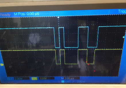
Look at your scope trace.
Two glaring things wrong:
1) The burst of something before the data starts. What is it?.
2) the start bit is short.
The first may well be that the bus biasing is not working correctly, or
be caused by noise (note below).
The second is almost certainly trying to send too quickly after enabling
the transceiver. Increase the delay after turning the transmit on.
There are also two major problems in the circuit.
The first is the lack of decoupling.
The PIC's themselves, and the MAX485 chips should have decoupling
capacitors immediately across their supply pins. Something like 0.1uF
ceramic capacitors across these points. Without these you will have
noise issues in the circuit.
The second is the supply is not connected. You are feeding power to just
one pair of the PIC's pins. This is _not_ acceptable. The PIC _requires_ all
supply pins to be connected. These actually feed different parts inside
the chip.
Also as a comment, The YwRobot unit you are using has very bad reviews
across the web, as the supply frequently fails causing issues and even
damaging components.
<http://ik1zyw.blogspot.com/2015/03/breadboard-power-supply-module.html>
Beware.....
Since I posted you have updated your picture & post, extending the delay.
You still have the burst of noise. Have you updated the PIC supply,
and added the decoupling?. Both required, required, required..... |
|
 |
emaxxenon
Joined: 21 Jan 2020
Posts: 42
|
|
| Posted: Thu Jan 23, 2020 3:51 am |
|
|
| Ttelmah wrote: | Look at your scope trace.
Two glaring things wrong:
1) The burst of something before the data starts. What is it?.
2) the start bit is short.
The first may well be that the bus biasing is not working correctly, or
be caused by noise (note below).
The second is almost certainly trying to send too quickly after enabling
the transceiver. Increase the delay after turning the transmit on.
There are also two major problems in the circuit.
The first is the lack of decoupling.
The PIC's themselves, and the MAX485 chips should have decoupling
capacitors immediately across their supply pins. Something like 0.1uF
ceramic capacitors across these points. Without these you will have
noise issues in the circuit.
The second is the supply is not connected. You are feeding power to just
one pair of the PIC's pins. This is _not_ acceptable. The PIC _requires_ all
supply pins to be connected. These actually feed different parts inside
the chip.
Also as a comment, The YwRobot unit you are using has very bad reviews
across the web, as the supply frequently fails causing issues and even
damaging components.
<http://ik1zyw.blogspot.com/2015/03/breadboard-power-supply-module.html>
Beware.....
Since I posted you have updated your picture & post, extending the delay.
You still have the burst of noise. Have you updated the PIC supply,
and added the decoupling?. Both required, required, required..... |
I added. Thank you for your help.
But the situation has not changed.
I just tried sending data. Sent successfully.
But the slave pic cannot send data to the master pic.
I think there is a problem in the program.
Communication stops when slave sends pic.
Sender:
| Code: | #include <16f877a.h>
#fuses HS,NOLVP,NOWDT,NOPROTECT
#use delay(clock=20000000)
#use rs232(baud=9600, xmit=PIN_C6, rcv=PIN_C7, enable=PIN_C5, ERRORS, stream=pic)
#include <stdlib.h>
void main()
{
while (TRUE)
{
if (input(PIN_A0)==1)
{
fputc('1');
}
if (input(PIN_A0)==0)
{
fputc('0');
}
}
}
|
Receiver:
| Code: |
#include <16f877a.h>
#fuses HS,NOLVP,NOWDT,NOPROTECT
#use delay(clock=20000000)
#use rs232(baud=9600, xmit=PIN_C6, rcv=PIN_C7, enable=PIN_C5, ERRORS, stream=pic)
#include <stdlib.h>
int16 x;
void main()
{
while (TRUE)
{
if (kbhit())
{
x = getc();
}
if (x=='1')
{
output_high(pin_b0);
output_low(pin_b1);
}
if (x=='0')
{
output_high(pin_b1);
output_low(pin_b0);
}
}
}
|
How should i add to this program?
If the slave pic received the information, I would like to send it back to the master pic.
Slave pic (input_state(pin_b0 == 1)) send to master --> "1"
Slave pic (input_state(pin_b1 == 1)) send to master --> "0"
Master pic (getc()==1) --> output_high(pin_b0)
Master pic (getc()==0) --> output_high(pin_b1)
I am trying to do this.
But there is a software problem.
--
I communicated smoothly with i2C.
Distance will be 5 meters.
Can I solve this problem using the P82B715TD component?
1 master will have 8 slave pic
Should I continue trying to communicate with MAX485? |
|
|
temtronic
Joined: 01 Jul 2010
Posts: 9106
Location: Greensville,Ontario
|
|
| Posted: Thu Jan 23, 2020 5:46 am |
|
|
Some comments about the hardware:
In your picture I do NOT see any caps at the xtal for either PIC !!
You also need 'decouplng/filter' caps at every device. Something like 100mfd/16v as well as a .1mfd/16v will help.
Those PICs have 2 VDD/VSS pins each and need to be connected to power
LED resistors should be 330r or 470r not 100r. While the LED may run at 20ma, it's a lot for a PIC to supply. I like 5-10ma, enough to see the LED but no power problems.
Pin A0 that you use as the 'trigger' or 'control', should have a small value cap (.1mfd) to gnd as a filter to reduce 'contact bounce' as well as a 10K 'load' resistor. It may be easier to rewire with a 10kr pullup, .1mfd filter and change program to 'ese' the pin going to ground ( if( input(PIN_A0)==0).....).
When YOU move the wire to trigger the event, the wire/hand become an antenna and pickup EMI, giving several false '1' signals. This can be seen if you put a scope probe on the pin. |
|
|
Ttelmah
Joined: 11 Mar 2010
Posts: 19221
|
|
| Posted: Thu Jan 23, 2020 6:30 am |
|
|
All agreed, but these plug in breadboards have so much internal capacitance,
that at 20MHz it probably provides enough capacitance to work for the
crystal load.
I've raised the need for both supplies and decoupling several times
and have yet to see any photo showing this. |
|
|
emaxxenon
Joined: 21 Jan 2020
Posts: 42
|
|
| Posted: Thu Jan 23, 2020 7:53 am |
|
|
Thank you for your help.
I don't have a capacitor for now. I will supply.
I made changes to the code.
Result: Successful.
My problem is due to the wait command.
The circuit worked when I entered a 100 ms standby command.
But I can't wait that long for communication.
Is my problem still due to hardware?
I ordered the necessary components.
But will this affect the speed?
My circuit: (not much change)
https://i.hizliresim.com/6DoBp0.jpg
New Master Code:
| Code: |
#include <16f877a.h>
#fuses HS,NOLVP,NOWDT,NOPROTECT
#use delay(crystal=20MHz,clock=20MHz)
#use rs232(baud=9600, xmit=PIN_C6, rcv=PIN_C7, enable=PIN_C5, ERRORS, stream=pic)
#include <stdlib.h>
void main()
{
while (TRUE)
{
if (input(PIN_A0)==1)
{
fputc('1');
delay_ms(100);
if (kbhit())
{
if(getc()=='1')
output_high(pin_b0);
output_low(pin_b1);
}
}
if (input(PIN_A0)==0)
{
fputc('0');
delay_ms(100);
if (kbhit())
{
if(getc()=='0')
output_high(pin_b1);
output_low(pin_b0);
}
}
}
}
|
New Slave Code:
| Code: |
#include <16f877a.h>
#fuses HS,NOLVP,NOWDT,NOPROTECT
#use delay(crystal=20MHz,clock=20MHz)
#use rs232(baud=9600, xmit=PIN_C6, rcv=PIN_C7, enable=PIN_C5, ERRORS, stream=pic)
#include <stdlib.h>
char x;
void main()
{
while (TRUE)
{
if (kbhit())
{
x = getc();
}
if (x=='1')
{
output_high(pin_b0);
output_low(pin_b1);
fputc('1');
delay_ms(100);
}
if (x=='0')
{
output_high(pin_b1);
output_low(pin_b0);
fputc('0');
delay_ms(100);
}
}
}
|
If I reduce the waiting time, the signal is distorted.
There will be 15 sensors connected to the Slave. These will detect the object. And there will be 8 slaves in total. So there will be 120 sensors. It will scan one by one. Scanning should end in 10 ms. I can't use the delay command. What should I do?
I had never used a wait command in i2c communication and it was working.
--
Edit: I made all the wait for 1 ms and it worked.
It does not work when there is no waiting.
Why is i2c not so?
I just want to send 1 or 0 information.
But I send it ascii. ('1' or '0')
Could the reason for the delay of the message be ascii?
Isn't it possible to send lice? |
|
|
temtronic
Joined: 01 Jul 2010
Posts: 9106
Location: Greensville,Ontario
|
|
| Posted: Thu Jan 23, 2020 8:13 am |
|
|
I think this....
fputc('1');
should really be..
fputc('1', pic);
It works now since there's only one USE RS232(..).
and FPUTC() takes the LAST stream named.
Also I would add 'PUT' to the #fuses list Power Up Timer allows the PIC to 'get organised' before executing main().
And I'd also add a delay_ms(250) as the first instruction in main(). While not technically necessary, adding it allows the PIC, peripherals and PSU to 'stabilize' before the real program runs.
You should be able to reduce your delay_ms(100); to maybe 5 or 10ms. Simply cut the time in half, compile, test, until it fails, then increase the delay 1-2 ms. This is a 'learn by doing' exercise.
Also you can 'define' pins with real names. It can make more sense AND if (when) you change a pin function, only one line of code (the 'define') needs to be changed.
You're making progress and that it GOOD ! |
|
|
Ttelmah
Joined: 11 Mar 2010
Posts: 19221
|
|
| Posted: Thu Jan 23, 2020 8:52 am |
|
|
With I2C, the slave device physically 'stops' the bus, until it accepts the data.
Result master will pause.
Serial is by default _duplex_. I2C and RS485 serial are only half duplex
(one direction at a time). Your receive can't see the reply until the other
end has sent it. It can't send until the bus is released.
2mSec should be an adequate delay.
Turn your baud rate up 250000bps. Then reduce the delay to 100uSec. |
|
|
asmallri
Joined: 12 Aug 2004
Posts: 1630
Location: Perth, Australia


|
|
| Posted: Thu Jan 23, 2020 5:39 pm |
|
|
| Quote: | Edit: I made all the wait for 1 ms and it worked.
It does not work when there is no waiting. |
So... please forgive me for not reading the entire thread, however a classic problem area with implementing RS485 communications is the disabling of the line driver before the last bit of the last byte has been transmitted out of the serial interface. This naturally corrupts the last byte. This is even more problematic when the serial peripheral has an output queue where it is capable of holding multiple bytes for transmission.
In that scenario, the reason a delay works is because the delay allows the serial output buffer to be purged before you disable the output driver.
_________________
Regards, Andrew
http://www.brushelectronics.com/software
Home of Ethernet, SD card and Encrypted Serial Bootloaders for PICs!! |
|
|
emaxxenon
Joined: 21 Jan 2020
Posts: 42
|
|
| Posted: Fri Jan 24, 2020 12:05 am |
|
|
| Ttelmah wrote: | With I2C, the slave device physically 'stops' the bus, until it accepts the data.
Result master will pause.
Serial is by default _duplex_. I2C and RS485 serial are only half duplex
(one direction at a time). Your receive can't see the reply until the other
end has sent it. It can't send until the bus is released.
2mSec should be an adequate delay.
Turn your baud rate up 250000bps. Then reduce the delay to 100uSec. |
Thank you so much.
It works! 250000bps -> 50uSec (minumum) I'm ok.
Now it's time to communicate with multiple PICs.
I will have questions again soon.  |
|
|
emaxxenon
Joined: 21 Jan 2020
Posts: 42
|
|
| Posted: Fri Jan 24, 2020 7:42 am |
|
|
Hello,
I will use the modbus example to communicate with slave pic.
I examined the protocol.
But i need help.
I want to send a message to the slave address.
And i want to read a message from my slave address.
I made the necessary serial settings.
"modbus_read_holding_registers"
I think reading is done with this function.
But I don't know how I can use it.
Not included in the example.
I searched but couldn't find it.
Can you give me a small example of writing and reading?
Master:
| Code: |
#include <Master.h>
#define MODBUS_BUS SERIAL
#define MODBUS_TYPE MODBUS_TYPE_MASTER
#define MODBUS_SERIAL_TYPE MODBUS_RTU
#define MODBUS_SERIAL_INT_SOURCE MODBUS_INT_RDA
#define MODBUS_SERIAL_RX_PIN PIN_C7
#define MODBUS_SERIAL_TX_PIN PIN_C6
#define MODBUS_SERIAL_ENABLE_PIN PIN_C5
#define MODBUS_SERIAL_BAUD 9600
#define MODBUS_REMOTE_ADDRESS 1
#include "modbus.c"
void main()
{
modbus_init();
while(TRUE)
{
How can I send data?
and how can I read data?
}
}
|
Slave:
| Code: | #include <Slave1.h>
#define MODBUS_BUS SERIAL
#define MODBUS_TYPE MODBUS_TYPE_SLAVE
#define MODBUS_SERIAL_TYPE MODBUS_RTU
#define MODBUS_SERIAL_INT_SOURCE MODBUS_INT_RDA
#define MODBUS_SERIAL_RX_PIN PIN_C7
#define MODBUS_SERIAL_TX_PIN PIN_C6
#define MODBUS_SERIAL_ENABLE_PIN PIN_C5
#define MODBUS_SERIAL_BAUD 9600
#define MODBUS_OUR_ADDRESS 1
#include "modbus.c"
void main()
{
modbus_init();
while(TRUE)
{
How can I send data?
and how can I read data?
}
}
|
I will be very happy if you help. |
|
|
temtronic
Joined: 01 Jul 2010
Posts: 9106
Location: Greensville,Ontario
|
|
| Posted: Fri Jan 24, 2020 7:53 am |
|
|
You do NOT need MODBUS to communicate between 2 PICs ! It's far too complicated and not required unless you HAVE a MODBUS device. Look at the CCS supplied RS485 example. Simple and easy to use and modify.
Have a look in the 'code library' here and searh for RS485, probably dozens of programs that may help.
There are 1,000s of examples of using RS485 for muliple devices, just use Google to find them. |
|
|
dluu13
Joined: 28 Sep 2018
Posts: 395
Location: Toronto, ON
|
|
| Posted: Fri Jan 24, 2020 8:07 am |
|
|
But op said he eventually wants to communicate between multiple devices. I thought modbus has a nice structure that really helped me along when I started.
Anyway, adapting the code in the example ex_modbus_slave.c and ex_modbus_master.c is a good start. There is implementation there of checking address, checking register address and whatnot. If you have a separate UART you can use to spit out values to a terminal it will help to verify your communications too. |
|
|
temtronic
Joined: 01 Jul 2010
Posts: 9106
Location: Greensville,Ontario
|
|
| Posted: Fri Jan 24, 2020 8:33 am |
|
|
MODBUS, like CAN is a 'top heavy', method of talking to several devices. One of those 'universal' protocols with 'features' most never use and don't need 99% of the time.
For over 3 decades I've done simple,reliable serial communcations to 'groups' of 32 devices using copper wire, up to 15 miles away, with a frame of 22 bits, at 24 baud. OK , it's not fancy but ultra reliable.
The great benefit of my KISS (Keep It Simpler Serial) is that it's easy to use, has tight compact code and very fault tolerant (even works with 1 wire cut). |
|
|
emaxxenon
Joined: 21 Jan 2020
Posts: 42
|
|
| Posted: Sat Jan 25, 2020 5:01 am |
|
|
1 master will have 8 slave pic.
I communicated 2 pic with rs485. Easy and hassle free.
But I couldn't create 1 master 8 slave logic.
I couldn't address.
Do you think there is a problem in the code below for 2 slaves?
Master:
| Code: |
#include <16f877a.h>
#fuses HS,NOLVP,NOWDT,NOPROTECT
#use delay(crystal=20MHz,clock=20MHz)
#define RS485_RX_PIN PIN_C7
#define RS485_TX_PIN PIN_C6
#define RS485_ENABLE_PIN PIN_C5
#use rs232(baud=9600, xmit=RS485_TX_PIN, rcv=RS485_RX_PIN, enable=RS485_ENABLE_PIN, ERRORS)
#include <rs485.c>
unsigned int data1[16]={"1"};
unsigned int data2[16]={"2"};
void main()
{
rs485_init();
while(true)
{
rs485_send_message(0x11,16,data1);
delay_ms(100);
rs485_send_message(0x12,16,data2);
delay_ms(100);
}
}
|
1.Slave
| Code: |
#include <16f877a.h>
#fuses HS,NOLVP,NOWDT,NOPROTECT
#use delay(crystal=20MHz,clock=20MHz)
#define RS485_RX_PIN PIN_C7
#define RS485_TX_PIN PIN_C6
#define RS485_ENABLE_PIN PIN_C5
#use rs232(baud=9600, xmit=RS485_TX_PIN, rcv=RS485_RX_PIN, enable=RS485_ENABLE_PIN, ERRORS)
#define RS485_ID 0x11
#include <rs485.c>
unsigned int data[16];
void main()
{
rs485_init();
while(true)
{
rs485_get_message(data, false);
if(data=="1")
{
output_high(pin_b0);
delay_ms(1000);
}
else
{
output_low(pin_b0);
}
}
}
|
2.Slave
| Code: |
#include <16f877a.h>
#fuses HS,NOLVP,NOWDT,NOPROTECT
#use delay(crystal=20MHz,clock=20MHz)
#define RS485_RX_PIN PIN_C7
#define RS485_TX_PIN PIN_C6
#define RS485_ENABLE_PIN PIN_C5
#use rs232(baud=9600, xmit=RS485_TX_PIN, rcv=RS485_RX_PIN, enable=RS485_ENABLE_PIN, ERRORS)
#define RS485_ID 0x12
#include <rs485.c>
unsigned int data[16];
void main()
{
rs485_init();
while(true)
{
rs485_get_message(data, false);
if(data=="2")
{
output_high(pin_b0);
delay_ms(1000);
}
else
{
output_low(pin_b0);
}
}
}
|
Edit:
Both pic's RX pins 1 and 2 are coming.
None of them take action. |
|
|
temtronic
Joined: 01 Jul 2010
Posts: 9106
Location: Greensville,Ontario
|
|
| Posted: Sat Jan 25, 2020 5:42 am |
|
|
hmm..
1) add PUT to the #fuses list. This Power Up Timer helps the PIC get 'ready' for proper operation. You can read what it really does in the datasheet,but I've always set it.
2) add a small delay just before main(). I usually use delay_ms(250);. Again this is just to allow the PIC and peripherals time to be properly configured.
These may fix the problem IF it's a startup condition. If it doesn't , then you KNOW it's not and may be a code problem.
Since it works 1M to 1 S, can you change the Slave addess ? IE change slave to 0x22, does that work? change again to 0x33, does that work? Or does it only work for 0x11( your original slave address )? |
|
|
|
|
You cannot post new topics in this forum
You cannot reply to topics in this forum
You cannot edit your posts in this forum
You cannot delete your posts in this forum
You cannot vote in polls in this forum
|
Powered by phpBB © 2001, 2005 phpBB Group
|

