 |
 |
| View previous topic :: View next topic |
| Author |
Message |
emaxxenon
Joined: 21 Jan 2020
Posts: 42


|
| 2 PIC Communication Problem |
 Posted: Tue Jan 21, 2020 8:46 am Posted: Tue Jan 21, 2020 8:46 am |
 |
|
Hi,
My english is very bad. I am sorry.
RS485 using communicate between; 1 Master pic and 1 Slave pic.
I am sending data from the master pic, but I cannot receive data from the slave pic.
Because I think I have a timing problem.
I am using MAX485. Pin_B7 = RE and DE control pin.
Master :
| Code: | #include <16f877a.h>
#fuses HS,NOLVP,NOWDT,NOPROTECT
#use delay(clock=20000000)
#use rs232(baud=9600,parity=N,xmit=PIN_C6, rcv=PIN_C7, bits=8)
#include <stdlib.h>
int16 x;
void main()
{
set_tris_b(0x00);
output_b(0);
set_tris_a(0xFF);
output_a(0);
set_tris_c(0x9F);
while (TRUE)
{
output_low(pin_b7);
if (input(PIN_A0)==1)
{
output_high(pin_b7);
fputc('1');
output_low(pin_b7);
}
if (input(PIN_A0)==0)
{
output_high(pin_b7);
fputc('0');
output_low(pin_b7);
}
if (kbhit())
{
x = getc();
}
if (x=='2')
{
output_high(pin_b0);
}
if (x=='3')
{
output_low(pin_b0);
}
}
} |
Slave :
| Code: | #include <16f877a.h>
#fuses HS,NOLVP,NOWDT,NOPROTECT
#use delay(clock=20000000)
#use rs232(baud=9600,parity=N,xmit=PIN_C6, rcv=PIN_C7, bits=8)
#include <stdlib.h>
int16 x;
void main()
{
set_tris_b(0x00);
output_b(0);
set_tris_a(0xFF);
output_a(0);
set_tris_c(0x9F);
while (TRUE)
{
output_low(pin_b7);
if (kbhit())
{
x = getc();
}
if (x=='1')
{
output_high(pin_b0);
output_high(pin_b7);
fputc('2');
output_low(pin_b7);
}
if (x=='0')
{
output_low(pin_b0);
output_high(pin_b7);
fputc('3');
output_low(pin_b7);
}
}
} |
What should I do?
Thank you for your help.
I searched the site on the subject. But I could not see an example that would be a solution.
I am trying to do:
Master:
A0 == 1 -> (master send -> slave) RE-DE High / fputc('1') / RE-DE Low
A0 == 0 -> (master send -> slave) RE-DE High / fputc('0') / RE-DE Low
x == 2 -> B0 High (master read) #not working code
x == 3 -> B0 Low (master read) #not working code
Slave:
x == 1 -> B0=1 // (slave send -> master) RE-DE High // fputc('2') // RE-DE Low
x == 0 -> B0=0 // (slave send -> master) RE-DE High // fputc('3') // RE-DE Low |
|
 |
temtronic
Joined: 01 Jul 2010
Posts: 9106
Location: Greensville,Ontario
|
|
| Posted: Tue Jan 21, 2020 9:09 am |
|
|
Some comments...
CCS does supply an example, in the 'examples' folder, I think it's named EX_RS485.C.
If you press F11 while your project is open, the CCS manual should appear. Look at the 'USE RS232(...keywords...)' for correct syntax and keywords.
ENABLE is the one that defines which pin you want to automatically control RE +DE.
You also need to add 'ERRORS' to the USE RS232(...keywords...). This will keep the UART from 'locking up'.
Also you can remove the SET_TRIS() code, the compiler will AUTOMATICALLY take care of that for you.
hopefully others will reply as well... |
|
|
Ttelmah
Joined: 11 Mar 2010
Posts: 19221
|
|
| Posted: Tue Jan 21, 2020 10:42 am |
|
|
If you are disabling receive, when you are transmitting, the line feeding the
RX input on both PICs, need a pullup resistors on them. Otherwise when you
transmit, you may well receive spurious characters as this line floats.
The RS485 bus itself also needs to have it's termination biased, so it
only sees data when it is actually driven.
<https://www.edn.com/understanding-rs-485-passive-fail-safe-biasing/>
Both Maxim and Texas do have later transceivers that have biasing built
in, but for the standard MAX485, this is required. |
|
|
temtronic
Joined: 01 Jul 2010
Posts: 9106
Location: Greensville,Ontario
|
|
| Posted: Tue Jan 21, 2020 10:59 am |
|
|
AS Mr. T. points out, you've got to get the Hardware correct BEFORE getting the Software .
The pullups are important, and be sure the wiring is correct! A to A, B to B. Don't 'flip them' A to B, B to A.....
Jay |
|
|
dluu13
Joined: 28 Sep 2018
Posts: 395
Location: Toronto, ON

|
|
| Posted: Tue Jan 21, 2020 4:41 pm |
|
|
| If you have an oscilloscope, or a logic analyzer, use that to check whether the elections are getting through in the first place |
|
|
emaxxenon
Joined: 21 Jan 2020
Posts: 42
|
|
| Posted: Wed Jan 22, 2020 12:10 am |
|
|
Hi, thanks for the answers.
This is my real connection.
Link: https://i.hizliresim.com/yGBzan.png
The circuit doesn't work real life.
And the circuit doesn't work in simulation.
A0 = 1 --> master sending slave "1" --> S1 B0 = 1
S1 B0 = 1 --> slave sending master "2" --> B0 = 1 but "?"
Master Edit:
| Code: |
#include <16f877a.h>
#fuses HS,NOLVP,NOWDT,NOPROTECT
#use delay(clock=20000000)
#use rs232(baud=9600,parity=N,xmit=PIN_C6, rcv=PIN_C7, enable=PIN_C5, bits=8, ERRORS)
#include <stdlib.h>
void main()
{
while (TRUE)
{
if (input(PIN_A0)==1)
{
fputc('1');
if (getc()=='2')
output_high(pin_b0);
}
if (input(PIN_A0)==0)
{
fputc('0');
if (getc()=='3')
output_low(pin_b0);
}
}
}
|
Slave Edit:
| Code: |
#include <16f877a.h>
#fuses HS,NOLVP,NOWDT,NOPROTECT
#use delay(clock=20000000)
#use rs232(baud=9600,parity=N,xmit=PIN_C6, rcv=PIN_C7, enable=PIN_C5, bits=8, ERRORS)
#include <stdlib.h>
int16 x;
void main()
{
while (TRUE)
{
if (kbhit())
{
x = getc();
}
if (x=='1')
{
output_high(pin_b0);
fputc('2');
}
if (x=='0')
{
output_low(pin_b0);
fputc('3');
}
}
}
|
I checked EX_RS485.C file but i could not adapt.
What should i fix?
Edit: i checked master RX, Slave sending master "d2" not "2"
Master RX status: https://i.hizliresim.com/mXQJmP.png
Last edited by emaxxenon on Wed Jan 22, 2020 12:51 am; edited 3 times in total |
|
|
Ttelmah
Joined: 11 Mar 2010
Posts: 19221
|
|
| Posted: Wed Jan 22, 2020 12:40 am |
|
|
OK. Well you don't have the required pullups on the RXD lines, and you don't
have biasing on the RS485 lines. Both are needed. |
|
|
emaxxenon
Joined: 21 Jan 2020
Posts: 42
|
|
| Posted: Wed Jan 22, 2020 12:54 am |
|
|
| Ttelmah wrote: |
OK. Well you don't have the required pullups on the RXD lines, and you don't
have biasing on the RS485 lines. Both are needed. |
Final version
https://i.hizliresim.com/anV1VR.png
But,
Slave not sending master "2". Slave sending "d"
Slave not sending master "3". Slave sending "f"
Why?
"and you don't have biasing on the RS485 lines."
I do not understand. Can you explain please?
Thanks for help.
Edit Master:
| Code: | #include <16f877a.h>
#fuses HS,NOLVP,NOWDT,NOPROTECT
#use delay(clock=20000000)
#use rs232(baud=9600,parity=N,xmit=PIN_C6, rcv=PIN_C7, enable=PIN_C5, bits=8, ERRORS)
#include <stdlib.h>
void main()
{
while (TRUE)
{
if (input(PIN_A0)==1)
{
fputc('1');
if (getc()=='d') /////// But slave sending 2
output_high(pin_b0);
}
if (input(PIN_A0)==0)
{
fputc('0');
if (getc()=='f') /////// But slave sending 3
output_low(pin_b0);
}
}
} |
EDIT:
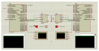
Data sending status in simulation
(Master TX - Slave RX)
https://i.hizliresim.com/P7ylQ8.png
Data sending status in real
(Master TX Status)
https://i.hizliresim.com/gP7O2Z.jpg
After RX connecting vcc with resistor
(Master TX Status)
https://i.hizliresim.com/zG60aO.jpg
Circuit didn't work in real life.
Data is not sent after connecting MAX485. |
|
|
PCM programmer
Joined: 06 Sep 2003
Posts: 21708
|
|
| Posted: Wed Jan 22, 2020 2:28 am |
|
|
Learn to use Google to search for answers.
Go to http://www.google.com and search for this:
There are many, many websites that teach everything about RS485 biasing. |
|
|
emaxxenon
Joined: 21 Jan 2020
Posts: 42
|
|
| Posted: Wed Jan 22, 2020 2:55 am |
|
|
| PCM programmer wrote: | Learn to use Google to search for answers.
Go to http://www.google.com and search for this:
There are many, many websites that teach everything about RS485 biasing. |
Thank you.
I researched and I think I'm on the right track.
My circuit diagram
https://i.hizliresim.com/3OmEW4.png
But still not working in real life.
Everything is exactly the same.
Edit:
My circuit:
https://i.hizliresim.com/gP7O1O.jpg
Max485 connected with jumper cable (20cm)
Do i need resistance? |
|
|
PCM programmer
Joined: 06 Sep 2003
Posts: 21708
|
|
| Posted: Wed Jan 22, 2020 4:04 am |
|
|
| emaxxenon wrote: |
But,
Slave not sending master "2". Slave sending "d"
Slave not sending master "3". Slave sending "f"
Why?
|
You need to analyze the data. Apparently, your problem is that the slave
is sending a 'd' character, but the master is receiving a '2'.
So, look at the bit patterns. Find a suitable ASCII chart on the net. Example:
http://web.alfredstate.edu/faculty/weimandn/miscellaneous/ascii/ascii_index.html
| Code: |
'd' bit pattern transmitted is: 01100100
'2' bit pattern received is: 00110010
|
Notice the received bits are equal to the transmitted bits, except they are
shifted to the right by 1 bit.
The PIC's UART transmits data LSB first. See Figure 10-1 in the 16F877A data sheet, on page 115 in the Acrobat reader:
https://ww1.microchip.com/downloads/en/devicedoc/39582b.pdf
So, your circuit or your code is causing the PIC to miss the first (LSB) bit.
Or it may be your testing method or software is causing the problem.
Or i'ts the compiler, some issue with the Enable pin. |
|
|
Ttelmah
Joined: 11 Mar 2010
Posts: 19221
|
|
| Posted: Wed Jan 22, 2020 5:05 am |
|
|
On the biasing, you are not applying enough. It needs to give 200mV to
ensure the '0' is seen. You have two 330R resistors in parallel, but only
5K of bias resistor. If you look at the example circuit you give the link to
they are using 560R for the bias....
Now it is impossible to tell from your photograph whether you have the
other resistors on the RX pins for the PIC. Again the example you point to
correctly shows these. Do you have these?. They are needed.
Is your intention 'long term', to have the RS485 going a significant distance?.
If so, the correct layout, is to have termination at each end of the bus wire
(within just a few tens of mm), Bias at one end only, but termination at both.
The value of the termination should be selected to give a reasonably good
impedance match to the wire of the bus. So if (for instance) this is network
cabling (that has about 100R impedance), you should be looking to have
perhaps a 110R resistance at each end. For this sort of cable I use a 110R
at the non biased end, and 220R, with 470R for the two bias resistors at
the other end.
This gives an equivalent impedance of 113R at this end. The two bias
resistors are in parallel with the terminating resistor in terms of the
impedance match.
Until the biasing is right, you risk the receiving end 'seeing' the transceiver
being 'off' as giving data.....
Once this is done, then we start having to ask other questions. |
|
|
Ttelmah
Joined: 11 Mar 2010
Posts: 19221
|
|
| Posted: Wed Jan 22, 2020 5:36 am |
|
|
Lets start with an explanation.
You are sitting with both devices listening to the bus.
Now nothing is driving the bus then, except the biasing.
At this point the PIC _must_ see '1' on it's RX input.
The bus biasing ensures this happens.
If it is not enough, then you risk getting odd characters received.
Then you go to transmit. RE set high. At this point the receive
transceiver turns off. Now the PIC UART will still receive characters
if anything does arrive on the RX pin. The pull up on the RX pin ensures
it does not receive anything at this time. If it does, then again you risk
receiving wrong characters.
So you need both the bus biased, and the PIC RX pins biased to give
correct reception. |
|
|
temtronic
Joined: 01 Jul 2010
Posts: 9106
Location: Greensville,Ontario
|
|
| Posted: Wed Jan 22, 2020 7:10 am |
|
|
re: ... The circuit doesn't work real life.
You're right, it never, ever will. There are serious basic hardware problem with that schematic. |
|
|
emaxxenon
Joined: 21 Jan 2020
Posts: 42
|
|
| Posted: Wed Jan 22, 2020 11:48 pm |
|
|
Hello,
I arranged the circuit. This is seen on the oscilloscope.
Blue signal = Master: TX
Yellow signal = Slave: RX
Master sending "1" -> Slave
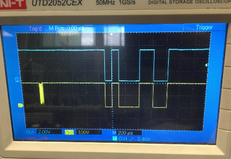
But it doesn't work. What is sent on the signal?
"1" is sent in the program.
If this is "1", the circuit should work. (yellow signal)
This is my circuit:
https://i.hizliresim.com/r0AvXN.jpg
Connected to vcc with RX 10K
100ohm connected between A and B.
Connected to vcc with A 330ohm.
Connected to gnd with B 330ohm.
I changed the resistance values, but the result is almost the same.
| temtronic wrote: | re: ... The circuit doesn't work real life.
You're right, it never, ever will. There are serious basic hardware problem with that schematic. |
How should I do my circuit?
Last edited by emaxxenon on Thu Jan 23, 2020 1:06 am; edited 4 times in total |
|
|
|
|
You cannot post new topics in this forum
You cannot reply to topics in this forum
You cannot edit your posts in this forum
You cannot delete your posts in this forum
You cannot vote in polls in this forum
|
Powered by phpBB © 2001, 2005 phpBB Group
|

