| View previous topic :: View next topic |
| Author |
Message |
temtronic
Joined: 01 Jul 2010
Posts: 9498
Location: Greensville,Ontario


|
|
 Posted: Sat Nov 18, 2017 6:43 am Posted: Sat Nov 18, 2017 6:43 am |
 |
|
You may want to 'cut the cord' and disconnect the PIC from the PC for some testing.
Replace the PIC project with a 'loopback' wire from the TTL<>USB modules TX and RX TTL pins.
Use any Terminal program and every key pressed on the keyboard should be displayed on the PC screen.
1st test setup will have the module attached to the PC.
2nd test setup, connect the module to a USB 'extension' cable. You probably already have that one.
Once you see that it works for simple key presses, then cut a VB program to send a 'data packet' of 64 bytes. Be sure to use KNOWN data, like 'The quick brown fox...' NOT just random characters. Send in a loop, say 1 per second.
Run, sit back and observe what happens...
If it fails in 'setup 1' it's and PC problem (OS or MB), if it passes #1, fails #2...then the USB extension cable is probably faulty.
If it passes all combinations of the above tests then I suspect the PIC hardware or software is at fault.
As a 'reference' I've run a 64MHz PIC18F46K22 as follows:
PC USB> USB<>TTL module>PIC UART1
UART1 > UART2
UART2>UART1
UART1> TTL<>USB Module
This 'daisy chained loopback' configuration ran both UARTS at 115K200 for days with NO data problems. The modules are cheap ($2 back then) offshore, having both 5 and 3V options, power and data LEDs.
There's a 1M USB cable, magic, spring loaded, coils up like old window blinds did...very small wires too ! It's the same type I use to connect PICKit3 to my XP PC.
Jay |
|
 |
Ttelmah
Joined: 11 Mar 2010
Posts: 19876
|
|
| Posted: Sat Nov 18, 2017 11:58 am |
|
|
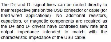
| Just try putting 22R resistors in the D+ and D- lines close to the PIC (just cut the wire/track and insert these in line). You will see these on a lot of USB devices. They help massively in reducing reflections at the end of the bus if there is a slight impedance mismatch. |
|
|
georpo
Joined: 18 Nov 2008
Posts: 281
Location: Athens, Greece.
|
|
| Posted: Sun Nov 19, 2017 10:33 am |
|
|
Today I tried on a windows 10 laptop with the same error results.
By now I have modified the vb code to send a detach command to the PIC
and reopen the comm port so I never get stuck anymore. I have a variable that increments every time this happens and I have to say that I get disconnected 1-2 times per minute.
I also have to admit that this pcb was not meant to have USB so I have the D+ and D- lines connected with wire to the side of the pcb where the USB plug is soldered.
Finally I hope that when I assemble the proper designed pcb the problems will be less.
_________________
George. |
|
|
temtronic
Joined: 01 Jul 2010
Posts: 9498
Location: Greensville,Ontario
|
|
| Posted: Sun Nov 19, 2017 10:46 am |
|
|
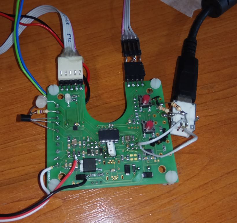
well a picture IS worth 1,000 words !
I'd replace those two grey wires from the USB connector to the PCB with 22r resistors, as Mr. T said. It is important that both D+ and D- wires are the same length. It will help reduce(not eliminate) reflection problems.
I am curious as to what the PCB does of course......
Jay |
|
|
georpo
Joined: 18 Nov 2008
Posts: 281
Location: Athens, Greece.
|
|
| Posted: Sun Nov 19, 2017 11:02 am |
|
|
I also tried with 22R resistors on both lines but I removed them after reading page 339 of the 30000684B.pdf manual:
This pcb will measure ambient temperature and open a valve that will let water flow from the plumbing network of a house in case the temperature is near freezing point.
This way it is supposed to prevent pipes breaking from ice...
I added USB in order to change parameters temperature etc.
And let me correct myself. The pcb was supposed to have USB but not with this side plug.
Of course I will make the loopback tests and see what happens.
_________________
George. |
|
|
Ttelmah
Joined: 11 Mar 2010
Posts: 19876
|
|
| Posted: Sun Nov 19, 2017 12:42 pm |
|
|
The resistors are not needed _if your PCB circuit has the right impedance_. This is what the data sheet tells you.
However if there is a mismatch, because (for instance) there is a ground plane close to the USB pins, the resistors help.
Try them.
It is also necessary to have the two lines very close to the same length. In the picture one line is a lot longer than the other. Currently two lines without a properly spaced ground, means these will be functioning as if these are stubs. Huge amounts of reflection. Not surprised the USB is having real problems.... |
|
|
temtronic
Joined: 01 Jul 2010
Posts: 9498
Location: Greensville,Ontario
|
|
| Posted: Sun Nov 19, 2017 5:01 pm |
|
|
I did a 'run around' on the USB hardware/software issue years ago. It's actually cheaper and far more reliable to just buy a $2 TTL<>USB module.
I don't so production runs of 100 let alone 10,000 so it's easier to just buy the modules. We all hear 'horror stories' anout USB 'issues' and I learned 40 years ago, it's best to spend a buck extra up front and KNOW the product will work reliably for decades. |
|
|
|


