| View previous topic :: View next topic |
| Author |
Message |
doguhanpala
Joined: 05 Oct 2016
Posts: 120


|
| bluetooth connection can not start |
 Posted: Fri Jun 09, 2017 7:51 am Posted: Fri Jun 09, 2017 7:51 am |
 |
|
Hello everyone,
I want to send commands to 18f2550 via bluetooth HC-05. I am sending the data using Putty. Putty connects the com but even there is the black screen and I can not send or receive anything. After a few restarts, it starts to work normally and i can send and receive data succesfully. I am not sure what is the problem but in case of the mistake being in the software, I am putting the code here.
| Code: |
#include <18F2550.h>
#DEVICE ADC=10
#fuses INTRC_IO,NOWDT,NOMCLR,NOPROTECT,NOLVP,NODEBUG,NOBROWNOUT,CPUDIV1,VREGEN
#use delay(clock=8000000)
#use rs232(baud=9600, xmit=PIN_A4,rcv = PIN_A5,stream = bt)
int command_array[20] = {};
byte baglantikuruldu = 0;
void komutal();
void baglan();
void main()
{
delay_ms(2000);
while(true)
{
delay_ms(1000);
baglan();
komutal();
}
}
void baglan() // connection. after this, the code will wait for commands
{
int basla = 0;
while(!baglantikuruldu) //if 'o' did not come from pc wait for it
{
while(!kbhit(bt))
delay_us(10);
if(kbhit(bt))
{
basla = getc(bt);
if(basla == 'o') //if 'o' is received send 'k'
{
delay_ms(100);
printf("k");
baglantikuruldu = 1;
}
else
printf("!");
}
}
}
void komutal() //wait for commands
{
int i = 0;
while(!kbhit(bt))
delay_us(10);
if(kbhit(bt))
{
command_array[0] = getc(bt);
printf("%d",command_array[0]);
}
if (command_array[0] == 'b') //if begin id is correct, get commands on array
{
for(i=1;i<11;i++)
{
command_array[i] = getc(bt);
printf("%d\n\r",command_array[i]);
if(command_array[i] == 'f') //if one of the command is 'F', wait for finish id
{
break;
}
}
printf("bitti");
command_array[i+1] = getc();
printf("%d",command_array[i+1]);
if(command_array[i+1] != 'p')
{
delay_ms(100);
printf("NO FINISH ID");
}
else
{
delay_ms(100);
printf("READY!");
}
}
else
{
printf("NO START ID");
}
} |
I noticed something. If putty turns on the black screen and there is no communication, the current on Bluetooth decreases. When there is no comm, the current is 0 (the voltage source is not very sensitive). When there is communication the current is about 20 mA.
Any ideas? I am suspecting on the use rs232 line. I know there should be something else but is it the reason of my problem?
Thank you very much.
Best wishes.
Doğuhan |
|
 |
temtronic
Joined: 01 Jul 2010
Posts: 9631
Location: Greensville,Ontario
|
|
| Posted: Fri Jun 09, 2017 8:09 am |
|
|
| You should post a link to the bluetooth module you're using. Most are 3 volt devices and that PIC is a 5 volt, so hardware could be the issue. |
|
|
doguhanpala
Joined: 05 Oct 2016
Posts: 120
|
|
| Posted: Fri Jun 09, 2017 8:34 am |
|
|
| temtronic wrote: | | You should post a link to the bluetooth module you're using. Most are 3 volt devices and that PIC is a 5 volt, so hardware could be the issue. |
Hello temtronic
Thank you for your answer.
I use this module:
http://www.electronicaestudio.com/docs/istd016A.pdf
But the version i have has a regulator circuit 5-to 3.3v. I checked it with a multimeter. |
|
|
Ttelmah
Joined: 11 Mar 2010
Posts: 20054
|
|
| Posted: Fri Jun 09, 2017 11:22 am |
|
|
The HC05, has a regulator to run the chip off 5v, but this does not ensure that the signals coming back to the PIC have the required voltage to drive the PIC input. If you look carefully at the sheet, it says "1.8 to 3.6v I/O". Your PIC has 5v I/O.
First you need a divider resistor pair on the TX from the PIC to the module:
<https://electronics.stackexchange.com/questions/280500/why-do-you-have-to-use-a-voltage-divider-with-hc-05-bluetooth-module-arduino>
Then separately you have the problem that while the Arduino has a Vih of 2.4v, so will accept the output from the chip, the serial input on your PIC has a Vih of 4v, which is 'borderline' (may work but not reliably). You need a level converter between the HC05 serial output, and the PIC's serial input.
I've used the HC05 into a level converter, and they are then very reliable. Without a converter, you are never going to get reliability.
These modules:
<http://www.rhydolabz.com/wiki/?p=8956>
have the HC05 and the 5v interfacing built in. |
|
|
temtronic
Joined: 01 Jul 2010
Posts: 9631
Location: Greensville,Ontario
|
|
| Posted: Fri Jun 09, 2017 12:06 pm |
|
|
Had a 'hunch' it was the 5 volt PIC vs 3 volt peripheral.
The EASY solution is to use a 3 volt rated PIC ! Those with 'L' in their designation should be fine. I know the 18F46K22 DOES run full speed at 3 volts. One of the many reasons I chose it several years ago.
Some potential problems with using logic level conversion are
space
wiring
cost
speed
always nice to have options......
Jay |
|
|
doguhanpala
Joined: 05 Oct 2016
Posts: 120
|
|
| Posted: Mon Jun 12, 2017 3:20 am |
|
|
Hello again
Thank you for your answers and sorry for late reply. In order to apply your suggetions, i want to confirm that i understood you correctly.
So, i am going with baby steps.
There are 2 types of modules as i understand.
First one is this http://www.robotistan.com/hc05-bluetooth-serial-modul-hc05-bc417-bluetooth-to-serial-port-module-2102-82-B.jpg
The picture in datasheet is something like this.
The other version is this(this is the one i have)
http://www.martyncurrey.com/wp-content/uploads/2015/08/HC-05-FC-114-HC-06-FC-114_1200.jpg
So the version i have has regulator. I measured it with multimeter and saw the voltage on vcc is 3.3v
Ttelmah said, i should pay attention on rx and tx pins also because they should be 3.3v but i use pics pins directly and give them 5V.
My circuit is like this now.
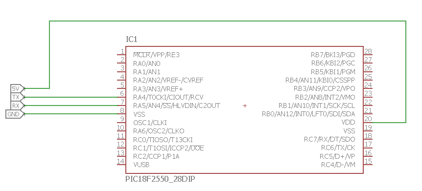
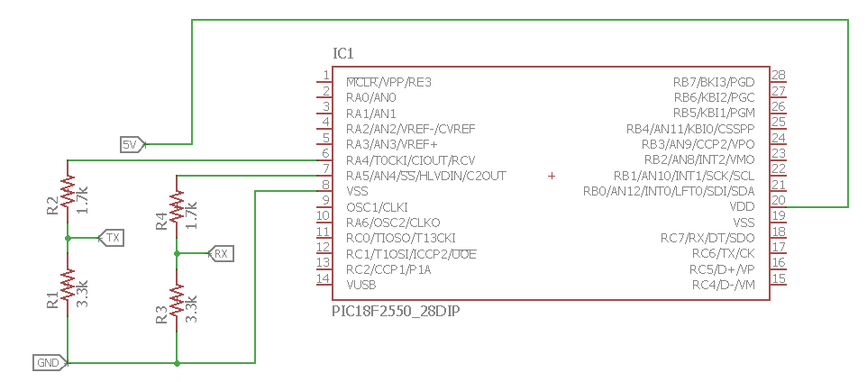
As i understood you suggest me to make a voltage divider and reduce the 5v on rx and tx to 3.3v. i used voltage divider with 2 resistors.
Is this ok?
edit: i have another question also. do i need to do this on hm-10 also. anyone encountered the problem?
note: i tried the voltage divider on the link Ttelmah shared. I think it worked, i tried connecting hc-05 10 times in a row and it did not fail once(before that i could not get 3 times in a row)
Thank you so much Ttelmah!
Jay, i cannot use 3v pic, the project requiers 5v, my module will supply voltage to another motor driver module but thank you for answer and suggetions. |
|
|
Ttelmah
Joined: 11 Mar 2010
Posts: 20054
|
|
| Posted: Mon Jun 12, 2017 6:24 am |
|
|
The attenuation is wanted on the pin coming in to the module (so PIC 5v out to the 3.3v module), but the other way you need _amplification_ (3.3v from the module into a PIC pin needing 4v).
Look at the sticky at the top of the forum on connecting an SD card to the PIC. There is a link there to an example circuit for doing this.
The problem is that the output pin from the module _does not give enough voltage to drive the PIC input_.... |
|
|
doguhanpala
Joined: 05 Oct 2016
Posts: 120
|
|
| Posted: Mon Jun 12, 2017 8:41 am |
|
|
| Ttelmah wrote: | The attenuation is wanted on the pin coming in to the module (so PIC 5v out to the 3.3v module), but the other way you need _amplification_ (3.3v from the module into a PIC pin needing 4v).
Look at the sticky at the top of the forum on connecting an SD card to the PIC. There is a link there to an example circuit for doing this.
The problem is that the output pin from the module _does not give enough voltage to drive the PIC input_.... |
Thank you so much Ttelmah! |
|
|
|


