 |
 |
| View previous topic :: View next topic |
| Author |
Message |
Ttelmah
Joined: 11 Mar 2010
Posts: 19222


|
|
 Posted: Thu Feb 02, 2017 8:01 am Posted: Thu Feb 02, 2017 8:01 am |
 |
|
You won't get to 3.4MHz with the PIC. Read the data sheet. Look at how the I2C is clocked. You can then work out the maximum it can generate.
I thought you had launched a separate thread using an SPI DAC?. This supports much faster speeds. Even better, no start and stop needed.
With I2C, BRG divisors of 0, 1 & 2 are not legal.
So the fastest supported is:
Fosc/16
With SPI, the fastest supported is Fosc/4. Then remove the start and stop transactions, and you have a speed at least perhaps 6* faster. |
|
 |
viki2000
Joined: 08 May 2013
Posts: 233
|
|
| Posted: Thu Feb 02, 2017 9:27 am |
|
|
Yes, I was thinking to test in parallel and see the limit of I2C approach 1st.
You say:
| Quote: | "So the fastest supported is:
Fosc/16" |
That would be fine with me, because 18F45K20 with 64MHz clock would then provide 64MHz/16=4MHz.
I would like to test that.
I just need some info about that High Speed Master Mode Code. |
|
|
Ttelmah
Joined: 11 Mar 2010
Posts: 19222
|
|
| Posted: Thu Feb 02, 2017 9:51 am |
|
|
As that would be over the maximum supported by the slave chip, that would be rather silly. However you also need the active pull-ups as already mentioned. You can get a bit above specifications without these, but as you get faster they become more and more essential.
Honestly pushing I2C this fast is asking for even more problems.
SPI is designed for higher speeds (active transceivers in both directions). |
|
|
viki2000
Joined: 08 May 2013
Posts: 233
|
|
| Posted: Thu Feb 02, 2017 1:00 pm |
|
|
But I did not intended to drive it at 4MHz. I just wanted to show that if the PIC can 4MHz according with your proposal, then for sure can also 3.4MHz, the max. of MCP4725.
Now, if I understand right, when comes to higher speeds than 400 KHz of I2C, as these high speeds 3.4 Mbit/s, then your recommendation is drop it, forget it, close the case, because it makes only trouble and I should focus on SPI. Is that right? |
|
|
Ttelmah
Joined: 11 Mar 2010
Posts: 19222
|
|
| Posted: Thu Feb 02, 2017 1:47 pm |
|
|
On I2C, there are four different speed standards.
Standard mode - 100kb/s max
Fast mode - 400kb/sec max
Fast mode+ - 1Mb/sec max
High speed mode - 3.4Mb/sec max.
HS mode requires active termination. So the terminator actually switches to give a faster edge. Also HS mode changes the way that clock stretching is handled. The PIC can drive Fast mode+, but does not as standard support HS mode (though it's drivers can actually generate the higher current this involves, and it is possible to drive HS with a PIC, but it requires custom PIC drivers, and a lot of luck).
Now all the faster modes will become relatively hard to handle.
Generally in electronics, one of the things to learn is that for reliability always work 'inside' specs, don't push up towards limits if you want reliability.
Now, honestly you are making a lot of work for yourself. If I wanted a half wave like this, I'd actually generate a full wave, and then rectify it.
Why?.
The reason is the harmonics. It is far easier to synthesise a really clean sinewave, since you can then just use a filter to reject the quantisation noise.
Then I'd not fiddle around with a PIC and DAC. Instead use a chip designed to do the job. There are sine synthesiser chips on the market that are able to do a much better job. |
|
|
temtronic
Joined: 01 Jul 2010
Posts: 9107
Location: Greensville,Ontario
|
|
| Posted: Thu Feb 02, 2017 3:54 pm |
|
|
Maybe it's just me but I keep looking at this post and think it's like using a sledgehammer to hit a tack. Way overkill for the job, too much time spent when you consider what Mains power really looks like. Or am I missing 'something'?
Jay |
|
|
asmboy
Joined: 20 Nov 2007
Posts: 2128
Location: albany ny

|
|
| Posted: Thu Feb 02, 2017 7:45 pm |
|
|
FYI- an overcompensated scope probe can make glitches on step edges too -
but its hard to beat a plug board for spike generation |
|
|
viki2000
Joined: 08 May 2013
Posts: 233
|
|
| Posted: Tue Mar 21, 2017 9:11 am |
|
|
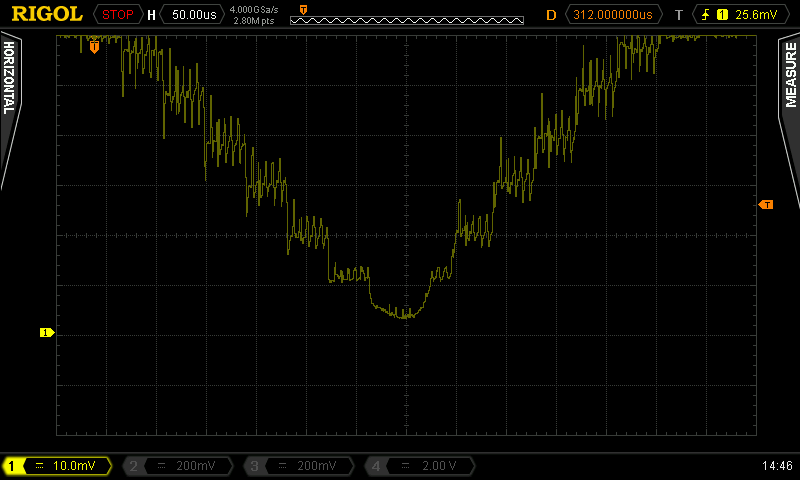
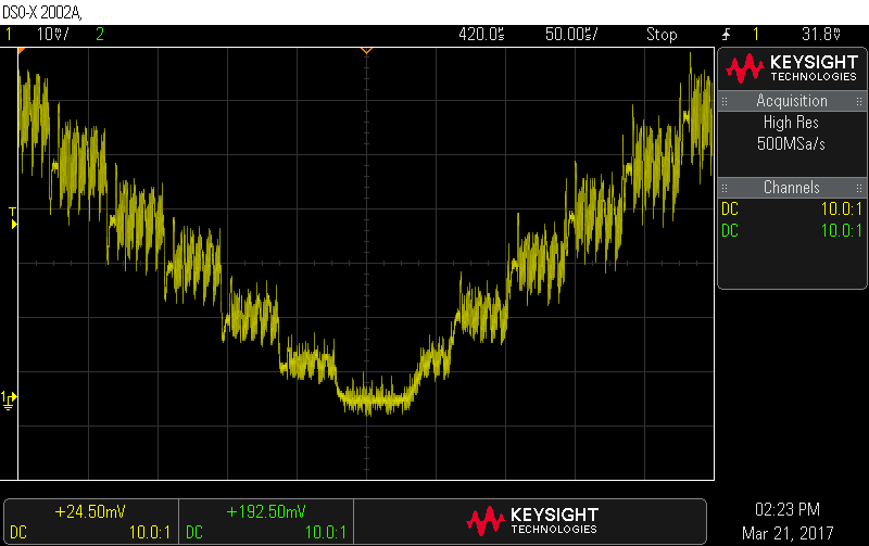
Here are my last observations over MCP4725 after a short test done yesterday and today.
I have tested the PIC Demo Board with PIC18F405K2, previously mentioned, with internal clock set at 64MHz using PLL. I measured the CLOCK OUT signal 16MHz (FOSC/4) to make sure I really have 64MHz inside the PIC.
I used a 9V battery with 5V 3-terminal regulator to make sure there is no ripple and noise from my 5V power adapter/supply.
When I zoom in with the oscilloscope at 1 step level of the signal, the noise is still there.
I have measured it with 2 different brand oscilloscopes, each with different probes.
I think it is due to high frequency of the I2C clock, maybe from inside the MCP4725.
Few weeks (or months?) ago I contacted Microchip to provide me an example about the 3.4Mbit/s of the MCP4725. The technician pointed fast to the MCP4725 board kits which they sell, but I told him that I checked their datasheets and is mentioned only 100KHz and 400KHz as I2C bus speed, so it makes no sense to buy and use them for test. I asked again about High Speed (HS) 3.4Mb/s example and since then a deep silence was laid.
Page 13:
http://ww1.microchip.com/downloads/en/DeviceDoc/51669a.pdf
Page 20:
http://ww1.microchip.com/downloads/en/DeviceDoc/51722a.pdf
Using PIC18F405K2 board at 64MHz I was able to increase a bit the speed on I2C bus. In software I was able to test “Fast=2250000”, so up to 2.25MHz, but in reality the I2C clock signal seen on oscilloscope was 1.6MHz.
I have reduced the pull-up resistors to 1K and later to 470ohm, but I could not g higher than the above limits.
Then for HS I have tried to add also the High Speed Master Mode Code as you may see disabled below code:
| Code: | i2c_start();
//i2c_write(0b00001000);
//i2c_start();
i2c_write(0b11001000); // Device address
i2c_write(0b1000000); // Internal Device address
i2c_write((sample & 0xFF0) >> 4); // Upper data bits (D11.D10.D9.D8.D7.D6.D5.D4)
i2c_write((sample & 0xF) << 4); //lower bits
i2c_stop(); // Stop
} |
It works with more delay by processing those instructions instead of higher speed.
I come slowly to one conclusion, that limitation is related with I2C hardware block, comes from the MSSP hardware module.
If you look here: http://www.microchip.com/forums/m654556.aspx
Someone said:
“So some 'off the cuff' calculation says that the I2C clock should be 1/16 the PIC instruction clock (XTAL/4)”
Which I found true for my 1st tests with PIC16F1825 working at 32MHZ and the I2C was blocked closed to 2MHz in software, was something like “Fast=1950000” maximum acceptable and when I had “Fast=2000000” then just stopped. I reality I had 1.3MHz I2C clock for “Fast=1950000” setting.
Nevertheless, 2MHz seems a hardware limit of I2C for PIC16F1825 working at 32MHZ and this can be calculated from datasheet.
http://ww1.microchip.com/downloads/en/DeviceDoc/40001440E.pdf
On the page 275 we have info about baud rate generator for MSSP module with a formula, a table below limited at 400KHz and the Note: “Values of 0x00, 0x01 and 0x02 are not valid for SSPxADD when used as a Baud Rate Generator for I2C. This is an implementation limitation.”
Then with 0x03 as minimum value for SSPxADD placed in the formula of the baud generator we get:
FCLOCK=FOSC/((SSPxADD+1)*4)=32MHz/((3+1)*4)=32MHz/(4*4)=32MHz/16=2MHz.
So, the clock of the I2C cannot be higher than 2MHz.
Then we just need to forget about using PIC16F1825 to test 3.4Mb/s I2C clock needed for HS OF MCP4725. And this applies to many other PICs.
My hope moved towards to 18F or 24F or other higher class PICs/controllers.
As I had the Using PIC18F405K2 board at 64MHz, I checked the datasheet of PIC18F405K2.
http://ww1.microchip.com/downloads/en/DeviceDoc/40001303H.pdf
It is a big book with 440 pages and perhaps I skipped by mistake something essential, but on the page 221 we have the info about baud rate generator for I2C, with a similar table only up to 400KHz and a similar formula and a similar Note: “The minimum SSPADD value for baud rate generation
is 0x03.”
The formula for baud rate is a bit twisted, but in fact is the same result:
“One half of the SCL period is equal to [(SSPADD+1) * 2]/FOSC. Therefore SSPADD=(FCY/FSCL) -1.”
That gave hope for 64MHz internal clock.
If ½ period of SCL = [(SSPADD+1) * 2]/FOSC, then a full period of SCL= 2*[(SSPADD+1) * 2]/FOSC=[(SSPADD+1) * 4]/FOSC
The FCLOCK=1/SCL=FOSC/[(SSPADD+1) * 4], which is the same as for PIC16F1825.
This time, due to FOSC=64MHz, the hardware limit of the MSSP should be 4MHz, so theoretically it should work with 3.4Mb/s required by MCP4725.
The practical tests show that MSSP do not output anymore over 1.6MHz real clock measured with the oscilloscope. I do not think that is any limitation coming from execution of the I2C subroutine, but I am not 100% sure. The idea is that if PIC16F1825 at 32MHz stopped its MSSP I2C at 1.3MHz real I2C clock, then I would have expected PIC18F45K20 at 64MHz to run the same I2C subroutine at double speed and if would have been any limitation from I2C subroutine at 1.3MHz then with double FOSC, to have limitation at almost double frequency 2.6MHz. But maybe inside the I2C CCS function the things are not working like that.
But as the limitation is at 1.6MHz real I2C clock, I tend to believe is a hardware limitation of the PIC18F45K20 MSSP. I see no signals coming out of the PIC18F45K20 I2C clock pin when I increase over “Fast=2250000”. Of course I admit that I should have tried with current sources too instead of resistors, but the clock signal does not look so bad at the corners at 1.6MHz real I2C clock. I still think is a limitation of the PIC18F45K20 MSSP hardware, but it should be tested with lower code subroutine or just to measure the execution of the existing subroutine for final conclusion.
I just wanted to see how MCP4725 performs at 3.4Mb/s I2C, because for the rest I learned my lesson. For the practical simple application related with I2C and PIC, I should stick with 400 KHz max. if I want to rely on that communication. |
|
|
asmboy
Joined: 20 Nov 2007
Posts: 2128
Location: albany ny
|
|
|
viki2000
Joined: 08 May 2013
Posts: 233
|
|
| Posted: Wed Mar 22, 2017 3:39 am |
|
|
Thank you for the calculated values, but my point this time was about maximum I2C speed, particularly how to achieve the 3.4Mbit/s claimed by MCP4725 and if there is any I2C MSSP hardware block inside to a PIC microcontroller to be able to run so fast and generally from where comes the limitations that I observed, because it seems a hardware limitation of the PIC.
I was thinking that having high speed between PIC and DAC, then I could increase the lookup table and I do not need any filter at all. It seems that I2C claimed speed 3.4Mb/s is not a good option when we refer at MCP4725 and we should stop at 400KHz; probably better results will be with SPI DAC, that I will analyze later when I have time.
Regarding your proposed values, they are good to smooth the signal, but they introduce some problems.
I have used MCP6002 OPAMP from Microchip. I have tried 1stage as you suggested, but also 2 stages.
The power supply is clean 9V battery with a + 5V 3-terminal regulator. The oscilloscopes were powered by a clean power supply, an AC programmable power supply with low distortion and the results are as you see below.
https://goo.gl/pqiWs7
There is an unwanted offset, even after the 1st stage of the Sallen Key filter. Besides that the waveform at the bottom, where it supposed to touch the zero line becomes more round instead of being sharp and the waveform per general becomes close to sine wave instead of rectified sine as I needed.
So, it is not good.
When you look from “distance”, zoom out if you want, with long time base for the oscilloscope, then the wave seems nice. But when we zoom in to look closely to one DAC step of the wave, then the noise can be still seen and measured. I have done that with 2 different DSO and different probes single-ended 1:10.
The noise is there and has around 12mV peak-peak roughly with possible maximum values of up to 35mV peaks and the period for one DAC step around 58us (frequency around 17KHz). |
|
|
temtronic
Joined: 01 Jul 2010
Posts: 9107
Location: Greensville,Ontario
|
|
| Posted: Wed Mar 22, 2017 4:55 am |
|
|
As Mr. T points out there isn't a PIC that can directly intereface with the I2C DAC and go '3.4Mbps'. As he pointed out I2C needs active terminations...My 'gut' tells me thats a LOT of specilaized sillicon under the hood so wait3-6 months and maybe Microchip will announce a PIC with it....I wonder if any micro has AT and what the cost is...side point..
As for the wave form comments. What is the power supply feeding the op amp consist of? Are both feeds equal(say +5.000 and -5.000),Are they properly filtered,for LF,MF and HF noise? Are the caps and resistors for the filter equal(10K000 and 10K000, 100nf000 and 100nf000). Not trying to be 'smart' but if the component values are not identical, that will affect performance.I know that tolerence(10%, 5%) does !as wellas 'temperature range'. Every DAC chip requires some form of R-C filter as that's part of the Analog portion of 'DAC' unless the DAC operates at extremely high speed(100MHz) to generate a very low frequency(100Hz).
Creating 'A from D' is a challenging task, 1/2 pure math , 1/2 bench test, and 1/2 luck. There's a LOT to get right before it works right...even PCB design is 'fun'.
Jay |
|
|
viki2000
Joined: 08 May 2013
Posts: 233
|
|
| Posted: Wed Mar 22, 2017 6:33 am |
|
|
| Quote: | | What is the power supply feeding the op amp consist of? Are both feeds equal(say +5.000 and -5.000) |
The power supply is clean 9V battery with a + 5V 3-terminal regulator. There is no dual power + 5 and -5V. |
|
|
temtronic
Joined: 01 Jul 2010
Posts: 9107
Location: Greensville,Ontario
|
|
| Posted: Wed Mar 22, 2017 7:22 am |
|
|
OK, I downloaded the DAC PDF...
some observations..
1) It says the Vref of the DAC is tied to VDD,so ANY variation in VDD( +5) WILL affect the DAC ! Yikes who in their right might thinks you can get 12 bit accuracy when you do that ,please raise your hands! The only way I could would be to use a precision reference device, with enough drive(current) to power the DAC as well as be the reference.It'd also have to be well filtered from the +9 source to insure ZERO ripple as ANY 'noise' will affect the DAC output.
2) Again, by the book, you need a 3K to 5K load on the output to keep it stable and accurate.
3)bipolar. I'm a 'dinosaur' and normally consider sine waves go +- from zero volts like 'Mains' power does.
4) your original post mentions a 1 v, rectifed output but your scope output links show a sine wave,so I assume you've not made that portion of the circuit?
Jay |
|
|
asmboy
Joined: 20 Nov 2007
Posts: 2128
Location: albany ny
|
|
| Posted: Wed Mar 22, 2017 7:27 am |
|
|
| Quote: | | Yikes who in their right might thinks you can get 12 bit accuracy when you do that ,please raise your hands! |
i get 12 bit accuracy on the A/D side of 12bit PIC 18F parts using Vdd as a reference. BUT i do it with 330uf of high quality Tantalum capacitor right at the Vdd pin AND feed that pin with a precision adjustable 1 A LDO regulator sourced from +12v ... it is quite possible but you do need to make sure the PIC is not doing any other I/O state changing during conversions.
it IS doable 100% -but it takes design planning to get there. |
|
|
viki2000
Joined: 08 May 2013
Posts: 233
|
|
| Posted: Wed Mar 22, 2017 7:34 am |
|
|
Answers specific to your numbers:
1) I do not care at this moment about that. I think I will give up with this DAC. I was just interested to see from where comes the bottle-neck speed when I want 3.4Mb/s.
2) I have tried with different resistors as load, but no chance when I try with I2C speeds higher than 400KHz. As in my case I have tried up to 1.6MHz I2C clock speed – measured on oscilloscope, additional noise appears.
3) The offset may be compensated probably with bipolar, but I cannot have it. I can have only unipolar +5Vdc.
4) Indeed, what I need is 1V rectified wave. The sinewave that you see in my last screenshots is due to OpAmp, the Sallen Key filter, from where I have also the offset.
This waveform 1V rectified sine 100Hz should be generated different, not with this simple I2C DAC.
The I2C should be used up to 400KHz. Over implies special needs and I want a very simple circuit.
I was more pushed by curiosity, is not a real project, to understand and analyze where is the problem with HS 3.4Mb/s. Is it really the hardware or I2C subroutine?
I will come back later with a timing analysis of the code used. That would be the last attempt here to understand the HS 3.4Mb/s I2C. |
|
|
|
|
You cannot post new topics in this forum
You cannot reply to topics in this forum
You cannot edit your posts in this forum
You cannot delete your posts in this forum
You cannot vote in polls in this forum
|
Powered by phpBB © 2001, 2005 phpBB Group
|

