|
 |
| View previous topic :: View next topic |
| Author |
Message |
vortexe90
Joined: 26 Feb 2013
Posts: 30
Location: Algeria


|
| ST7920 DRIVER for Chinese model |
 Posted: Sat Oct 25, 2014 3:24 am Posted: Sat Oct 25, 2014 3:24 am |
 |
|
hi guys, I drive a graphical LCD with the following driver, but it works a partial way, as I apply a "glcd_fillscreen (ON);" there is a part that will be displayed. Even all the operations made it appear in this section.
and graphical display model in the simulator "Proteus" works well, so I believe that there is a problem with the driver. Please help me I am very pressed in time
| Code: | #define rs PIN_C0 //COMMAND/DATA SELECT
#define rw PIN_C1 //READ/WRITE SELECT
#define e PIN_C2 //ENABLE SIGNAL
#define rst PIN_C5 //RESET SIGNAL
#define ON 1
#define OFF 0
#define XVAL 16 // 16 X 16 or 256 for there is 8 word values for the upper and lower
#define YVAL 32
#define GLCD_WIDTH 128
typedef union
{
int16 word;
int8 nbyte[2];
} Dots;
typedef struct
{
int1 refresh;
Dots pix[YVAL][XVAL]; // Max dimensions for display (x,y) = (128,32)
} GD_RAM; // (0,0) corresponds to upper lefthand corner.
GD_RAM gdram;
unsigned int8 glcd_readByte (unsigned int1 address)
{
unsigned int8 data; // Stores the data read from the LCD
if(address==1){
output_high(rs);
}
if(address==0){
output_low(rs);
}
output_high(rw);//GLCD_RW = RW_READ; // Set for reading
output_high(e);//GLCD_E = 1; // Pulse the enable pin
delay_us(1);
data=input_b(); // Get the data from the display's output register
output_low(e);//GLCD_E = 0;
return (data);
}
void glcd_check_busy(){
int1 busy=1;
output_low(rs); // LOW RS and High RW will put the lcd to
output_high(rw); // read busy flag and address counter
while(busy){ // will cycle until busy flag is 0
output_high(e);
if(!input(PIN_B7)){
busy=0;
}
output_low(e);
}
}
void glcd_instruction(unsigned char x){
glcd_check_busy(); //must be satisfied before sending instruction
output_low(rs); // LOW RS and LOW RW will put the lcd to
output_low(rw); // Write instruction mode
output_b(x); // 8bit data to bus
output_high(e); // enable
delay_us(1);
output_low(e); // disable
}
void glcd_data(unsigned char x){
glcd_check_busy();
output_high(rs); // HIGH RS and LOW RW will put the lcd to
output_low(rw); // Write data register mode
output_b(x);
output_high(e);
delay_us(1);
output_low(e);
}
void glcd_fillScreen (unsigned int1 color)
{
int8 v, h;
int16 d;
d = (color == ON ? 0xFFFFL : 0x0000L);
for (v=0; v < YVAL; v++)
{
for (h=0; h < XVAL; h++)
{
gdram.pix[v][h].word = d;
}
}
gdram.refresh = TRUE;
}
void glcd_update ()
{
int8 v, h;
if (gdram.refresh)
{
for (v=0; v <YVAL; v++)
{
glcd_instruction( 0x80 | v); // Set Vertical Address.
glcd_instruction( 0x80 | 0); // Set Horizontal Address.
for (h=0; h <XVAL; h++)
{
glcd_data( gdram.pix[v][h].nbyte[1]); // Write High Byte.
glcd_data( gdram.pix[v][h].nbyte[0]); // Write Low Byte.
}
}
gdram.refresh = FALSE;
}
}
void glcd_init_graph(){
delay_ms(40);
output_low(rst); //reset LCD
delay_us(1);
output_high(rst); //LCD normal operation
glcd_instruction(0x30); //set 8 bit operation and basic instruction set
delay_us(144);
glcd_instruction(0x0C); //display on cursor off and char blink off
delay_us(100);
glcd_instruction(0x01); //display clear
delay_ms(10);
glcd_instruction(0x06); //entry mode set
delay_us(72);
glcd_instruction(0x34); // Select extended instruction set.
delay_ms (10);
glcd_instruction(0x36); // Graphic display ON.
delay_ms (10);
glcd_fillScreen (OFF);
glcd_update ();
}
void glcd_init_basic(){
delay_ms(40);
output_low(rst); //reset LCD
delay_us(1);
output_high(rst); //LCD normal operation
glcd_instruction(0x30); //set 8 bit operation and basic instruction set
delay_us(144);
glcd_instruction(0x0C); //display on cursor off and char blink off
delay_us(100);
glcd_instruction(0x01); //display clear
delay_ms(10);
glcd_instruction(0x06); //entry mode set
delay_us(72);
}
void glcd_pixel(int8 x, int8 y, int1 color)
{
int8 v, h, b;
if(y>31){x += 128; y-= 32;};
v = y;
h = x/16;
b = 15 - (x%16);
if (color == ON) bit_set (gdram.pix[v][h].word, b);
else bit_clear (gdram.pix[v][h].word, b);
gdram.refresh = TRUE;
}
const int8 image[]={
0x00, 0x00, 0x00, 0x00, 0x00, 0x00, 0x00, 0x00,
0x00, 0x00, 0x00, 0x00, 0x00, 0x00, 0x00, 0x00,
0x00, 0x00, 0x00, 0x00, 0x00, 0x00, 0x00, 0x00,
0x00, 0x00, 0x00, 0x00, 0x00, 0x00, 0x00, 0x00,
0x00, 0x00, 0x00, 0x00, 0x28, 0x00, 0x00, 0x00,
0x00, 0x00, 0x00, 0x3b, 0xb0, 0x00, 0x00, 0x00,
0x00, 0x00, 0x00, 0xec, 0x8e, 0x00, 0x00, 0x00,
0x00, 0x00, 0x03, 0xf7, 0x6b, 0x00, 0x00, 0x00,
0x00, 0x00, 0x07, 0xbd, 0xb1, 0x40, 0x00, 0x00,
0x00, 0x00, 0x0f, 0xf7, 0xdd, 0xc0, 0x00, 0x00,
0x00, 0x00, 0x1f, 0xff, 0x6a, 0xb0, 0x00, 0x00,
0x00, 0x00, 0x1e, 0xff, 0xdb, 0x68, 0x00, 0x00,
0x00, 0x00, 0x3f, 0xdd, 0xfe, 0xf0, 0x00, 0x00,
0x00, 0x00, 0x37, 0xff, 0xb7, 0xa8, 0x00, 0x00,
0x00, 0x00, 0x3e, 0xd5, 0x5a, 0xfc, 0x00, 0x00,
0x00, 0x00, 0x7f, 0x6a, 0x4b, 0x74, 0x00, 0x00,
0x00, 0x00, 0x36, 0x91, 0x29, 0x7c, 0x00, 0x00,
0x00, 0x00, 0x3e, 0x44, 0x95, 0x5a, 0x00, 0x00,
0x00, 0x00, 0x3d, 0x11, 0x24, 0xfc, 0x00, 0x00,
0x00, 0x00, 0x3e, 0xa4, 0x4a, 0xb8, 0x00, 0x00,
0x00, 0x00, 0x36, 0x91, 0x25, 0x5c, 0x00, 0x00,
0x00, 0x00, 0x3e, 0xbc, 0x9f, 0xb8, 0x00, 0x00,
0x00, 0x00, 0x1d, 0x46, 0x51, 0x58, 0x00, 0x00,
0x00, 0x00, 0x0d, 0x79, 0x2e, 0xb4, 0x00, 0x00,
0x00, 0x00, 0x26, 0x54, 0x95, 0x90, 0x00, 0x00,
0x00, 0x00, 0x0a, 0x0a, 0x52, 0xb4, 0x00, 0x00,
0x00, 0x00, 0x12, 0xa0, 0xa4, 0x94, 0x00, 0x00,
0x00, 0x00, 0x0a, 0x4a, 0x2a, 0xa8, 0x00, 0x00,
0x00, 0x00, 0x05, 0x01, 0x51, 0x50, 0x00, 0x00,
0x00, 0x00, 0x05, 0x54, 0x2a, 0x20, 0x00, 0x00,
0x00, 0x00, 0x02, 0x09, 0x55, 0x50, 0x00, 0x00,
0x00, 0x00, 0x01, 0xa2, 0xa9, 0x00, 0x00, 0x00,
0x00, 0x00, 0x01, 0x10, 0x2a, 0x80, 0x00, 0x00,
0x00, 0x00, 0x01, 0xab, 0xac, 0x80, 0x00, 0x00,
0x00, 0x00, 0x01, 0x44, 0x15, 0x00, 0x00, 0x00,
0x00, 0x00, 0x01, 0x92, 0xaa, 0x80, 0x00, 0x00,
0x00, 0x00, 0x00, 0x24, 0xaa, 0x00, 0x00, 0x00,
0x00, 0x00, 0x00, 0x28, 0x94, 0x00, 0x00, 0x00,
0x00, 0x00, 0x00, 0x22, 0x4a, 0x00, 0x00, 0x00,
0x00, 0x00, 0x00, 0x14, 0x2a, 0x00, 0x00, 0x00,
0x00, 0x00, 0x00, 0x4a, 0xaa, 0x00, 0x00, 0x00,
0x00, 0x00, 0x00, 0x21, 0x55, 0x40, 0x00, 0x00,
0x00, 0x00, 0x02, 0x09, 0x55, 0x30, 0x00, 0x00,
0x00, 0x00, 0x02, 0x10, 0x52, 0x30, 0x00, 0x00,
0x00, 0x00, 0x0e, 0x05, 0x0a, 0x18, 0x00, 0x00,
0x00, 0x00, 0x1f, 0x00, 0x54, 0x0d, 0x00, 0x00,
0x00, 0x00, 0x56, 0x01, 0x24, 0x0d, 0x50, 0x00,
0x00, 0x02, 0xff, 0x00, 0x48, 0x06, 0xd4, 0x00,
0x00, 0x0d, 0xb5, 0x00, 0x10, 0x0b, 0x6b, 0xa0,
0x00, 0x77, 0xff, 0x80, 0x00, 0x06, 0xbd, 0x50,
0x03, 0x5b, 0x57, 0x00, 0x7c, 0x87, 0xee, 0xfc,
0x1d, 0xef, 0xfd, 0x80, 0x9e, 0x06, 0xb7, 0xaf
};
void glcd_plot_image(int width,int height,int x,int y,int inverse)
{
unsigned int i=0, j=0, k=0;
unsigned int16 count=0;
//glcd_fillScreen(OFF); //Clears the screen (opt.)
for(j=0;j<height;j++)
{
for(;i<width;)
{
for(k=8;k>0;k--){
if(inverse)glcd_pixel(i+x,j+y,~bit_test(image[count],(k-1)));
else glcd_pixel(i+x,j+y,bit_test(image[count],(k-1)));
i++;
}
count++;
}
i=0;
}
}
|
my prog test
| Code: |
#include <18F4620.h>
#device adc=8
#FUSES NOWDT //No Watch Dog Timer
#FUSES WDT128 //Watch Dog Timer uses 1:128 Postscale
#FUSES HS //High speed Osc (> 4mhz for PCM/PCH) (>10mhz for PCD)
#FUSES NOPROTECT //Code not protected from reading
#FUSES IESO //Internal External Switch Over mode enabled
#FUSES NOBROWNOUT //No brownout reset
#FUSES BORV21 //Brownout reset at 2.1V
#FUSES NOPUT //No Power Up Timer
#FUSES NOCPD //No EE protection
#FUSES STVREN //Stack full/underflow will cause reset
#FUSES NODEBUG //No Debug mode for ICD
#FUSES NOLVP //No low voltage prgming, B3(PIC16) or B5(PIC18) used for I/O
#FUSES NOWRT //Program memory not write protected
#FUSES NOWRTD //Data EEPROM not write protected
#FUSES NOEBTR //Memory not protected from table reads
#FUSES NOCPB //No Boot Block code protection
#FUSES NOEBTRB //Boot block not protected from table reads
#FUSES NOWRTC //configuration not registers write protected
#FUSES NOWRTB //Boot block not write protected
#FUSES FCMEN //Fail-safe clock monitor enabled
#FUSES NOXINST //Extended set extension and Indexed Addressing mode disabled (Legacy mode)
#FUSES PBADEN //PORTB pins are configured as analog input channels on RESET
#FUSES LPT1OSC //Timer1 configured for low-power operation
#FUSES MCLR //Master Clear pin enabled
#use delay(clock=20000000)
#include "st7920.h"
#include "GRAPHICS.C"
void main(){
setup_adc_ports(NO_ANALOGS|VSS_VDD);
setup_adc(ADC_OFF|ADC_TAD_MUL_0);
setup_psp(PSP_DISABLED);
setup_spi(SPI_SS_DISABLED);
setup_wdt(WDT_OFF);
setup_timer_0(RTCC_INTERNAL);
setup_timer_1(T1_DISABLED);
setup_timer_2(T2_DISABLED,0,1);
setup_comparator(NC_NC_NC_NC);
setup_vref(FALSE);
glcd_init_graph();
while(true){
glcd_fillscreen(ON); //turn all GLCD on
glcd_update(); //refresh
delay_ms(1000);
}
}
|
|
|
 |
Ttelmah
Joined: 11 Mar 2010
Posts: 20038
|
|
| Posted: Sat Oct 25, 2014 12:30 pm |
|
|
One thing leaping out before you blame the driver, is that you have the SPI enabled on the same port you are using to drive the display. This is the sort of thing that the simulator will ignore, but the real chip won't then work properly.....
SPI_SS_DISABLED, is the command to turn off the slave select bit on the SPI, _not_ the command to disable the SPI port.... |
|
|
vortexe90
Joined: 26 Feb 2013
Posts: 30
Location: Algeria
|
|
| Posted: Sat Oct 25, 2014 2:30 pm |
|
|
| Ttelmah wrote: | One thing leaping out before you blame the driver, is that you have the SPI enabled on the same port you are using to drive the display. This is the sort of thing that the simulator will ignore, but the real chip won't then work properly.....
SPI_SS_DISABLED, is the command to turn off the slave select bit on the SPI, _not_ the command to disable the SPI port.... |
Thank you very much for the advice sir, but the driver of the display why it displays in only part of the display, and this part is 16 by 32 bits, and sincerment I do not want to blame the driver.
thanks... |
|
|
vortexe90
Joined: 26 Feb 2013
Posts: 30
Location: Algeria
|
|
| Posted: Sun Oct 26, 2014 3:49 am |
|
|
this driver only displays in the upper left part, with a dimension of 16x32 pixel also only.
please is there a modification in the GLCD_to use all the area of displayer |
|
|
PCM programmer
Joined: 06 Sep 2003
Posts: 21708
|
|
| Posted: Sun Oct 26, 2014 5:30 pm |
|
|
Post a link to the website for your graphic lcd so we can read the
specifications on it. |
|
|
vortexe90
Joined: 26 Feb 2013
Posts: 30
Location: Algeria
|
|
|
temtronic
Joined: 01 Jul 2010
Posts: 9624
Location: Greensville,Ontario
|
|
| Posted: Mon Oct 27, 2014 6:47 am |
|
|
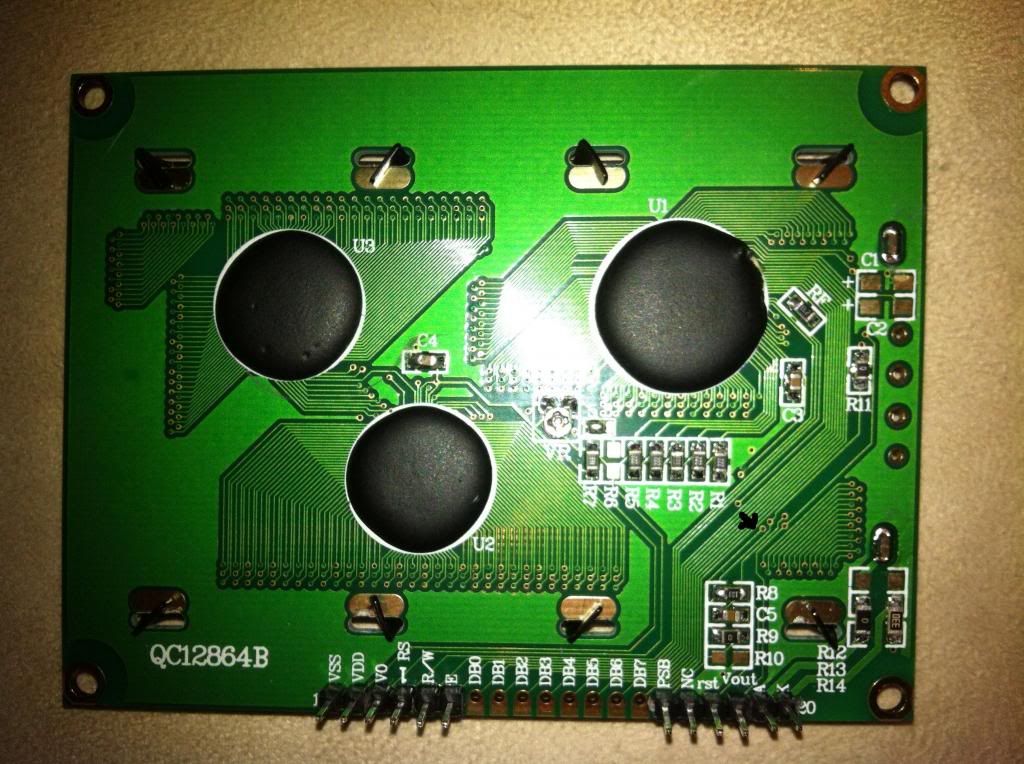
I don't use that display but
I looked at your code in the original post and it's for the PARALLEL data mode NOT the SERIAL mode...
when I look at the picture of your LCD in the last post, it appears to be using the SERIAL mode NOT PARALLEL mode as there are no connections to DB0...DB7.
So I have to ask you to clarify which MODE for the display are you using.
Unless I'm not seeing things correctly.
Jay |
|
|
vortexe90
Joined: 26 Feb 2013
Posts: 30
Location: Algeria
|
|
| Posted: Mon Oct 27, 2014 7:20 am |
|
|
| temtronic wrote: | I don't use that display but
I looked at your code in the original post and it's for the PARALLEL data mode NOT the SERIAL mode...
when I look at the picture of your LCD in the last post, it appears to be using the SERIAL mode NOT PARALLEL mode as there are no connections to DB0...DB7.
So I have to ask you to clarify which MODE for the display are you using.
Unless I'm not seeing things correctly.
Jay |
I use a parallel mode D0 to D7 but the model is from china, the routine that i post work only in the left upper part only ........why...???
thanks |
|
|
PCM programmer
Joined: 06 Sep 2003
Posts: 21708
|
|
| Posted: Mon Oct 27, 2014 9:32 am |
|
|
Just to clarify:
Did you take that photo of your LCD ? Are those the pin connections
on your LCD that you own ? Is it a recent photo ?
Do you actually have connections on your LCD to pins DB0-DB7 ?
Or, is that a stock photo from the lcd seller's website ? |
|
|
vortexe90
Joined: 26 Feb 2013
Posts: 30
Location: Algeria
|
|
| Posted: Tue Oct 28, 2014 2:25 am |
|
|
| PCM programmer wrote: | Just to clarify:
Did you take that photo of your LCD ? Are those the pin connections
on your LCD that you own ? Is it a recent photo ?
Do you actually have connections on your LCD to pins DB0-DB7 ?
Or, is that a stock photo from the lcd seller's website ? |
here is my LCD is mounted exactly as the following picture (for control, RS, RW and E) (for data D0-D7) pin is connected to VCC PSB for parallel mode

what surprised me is that the display works well, but it appears only in the upper left side with 16x32 pixel only too
For this reason, I doubt this driver posted above. I believe that every driver ST7920 are normally identical.
As Mr "PCM programmer" I simulate my project with the following model (see photo).
here is where I found the model I simulate with my project
http://forum.eepw.com.cn/thread/238647/1
For the serial mode there is a driver?
thanks... |
|
|
|
|
You cannot post new topics in this forum
You cannot reply to topics in this forum
You cannot edit your posts in this forum
You cannot delete your posts in this forum
You cannot vote in polls in this forum
|
Powered by phpBB © 2001, 2005 phpBB Group
|