 |
 |
| View previous topic :: View next topic |
| Author |
Message |
Nora
Joined: 23 Mar 2008
Posts: 50


|
| PIC16F877A keeps resetting |
 Posted: Mon Jul 25, 2011 7:32 pm Posted: Mon Jul 25, 2011 7:32 pm |
 |
|
Hello!
I am using the PIC16877A to switch a relay. I'm using an NPN circuit with a 2k resistor on the base.
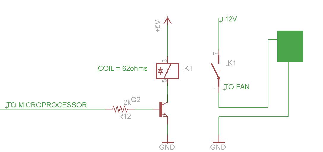
When I hold the pin B3 high, the PIC keeps resetting, causing the relay to chatter. I've also tried pin D3.
When I bypass the PIC and use a battery to energize the coil, the speaker (not a fan as indicated in image) that I am switching (7.5V, not 12V as indicated in image) stays on without chattering.
Conclusion: it is not the relay's electrical circuit (relay, transistor, resister), but something to do with the PIC's electrical circuit.
But what?
Thanks in advance for thoughts!
N_N |
|
 |
w2drz
Joined: 27 Dec 2006
Posts: 55
Location: Western New York - USA

|
|
| Posted: Mon Jul 25, 2011 7:59 pm |
|
|
Hi,
I do not see a reverse protect diode across the relay.
ALSO need to add a diode across the + to - of the FAN motor in your circuit.
Can use a 1N4148 or any diode in your build stuff,
diode bar is to the + voltage,
other diode lead to transistor & 2nd diode on fan motor.
The diodes are to provide a reverse voltage path for the collapsing relay coil
and fan motor when relay is switched off.
Without a diode the voltage can be hundreds to thousands of volts produced by the collapsing relay coil field. 
The switched off voltage spike can couple into surrounding circuits and/or destroy S.S. devices on your board. 
tom W2DRZ |
|
|
temtronic
Joined: 01 Jul 2010
Posts: 9641
Location: Greensville,Ontario
|
|
| Posted: Mon Jul 25, 2011 8:52 pm |
|
|
hmm..
If we believe the diagram, then the relay already has the protection diode inside.
What are the transistor specs? Perhaps it doen't have a high enough beta to properly work?
Is the PIC running off 5 volts, with a power supply of at least 2000ma(2 Amps)? The relay draws 80ma when on steady, turn on will draw 10x more(800ma) for a brief period.
without the PIC put 5 volts to the resistor and see if it works properly. |
|
|
gpsmikey
Joined: 16 Nov 2010
Posts: 588
Location: Kirkland, WA
|
|
| Posted: Tue Jul 26, 2011 10:01 am |
|
|
My first guess would be a grounding issue. Without a good solid ground configuration, when the transistor turns on to sink the load, it is pulling the ground UP causing the reset. Also make sure you have bypass caps across the vcc/gnd. Switching inductive loads can create all sorts of nasty things with many unintended consequences. As others have indicated, make sure the relay coil has the diode across it (the diagram shows it, but make sure it does have one). Another thing you can do (although you have to be careful to watch the timing) is put a small cap from the base of the transistor to ground. That cap in conjunction with the base drive resistor creates a RC time constant that slows down the turn on/turn off times of the transistor which reduces the inductive kicks from the load. The down side is then when you slow down the switching, you increase the time the transistor is in the linear mode as it switches and heating can be an issue. You can also create a problem if the relay opens/closes too slow.
mikey
_________________
mikey
-- you can't have too many gadgets or too much disk space !
old engineering saying: 1+1 = 3 for sufficiently large values of 1 or small values of 3 |
|
|
Ttelmah
Joined: 11 Mar 2010
Posts: 20090
|
|
| Posted: Tue Jul 26, 2011 11:56 am |
|
|
Other comment. Where does the energy go?.
The point about protection diodes, is that they route the energy _somewhere_. Normally (if there is one across the coil as hypothesised from the drawing), _into_ the supply rail. The effect will depend on how well smoothed this is. If there isn't significant reservoir capacitance on the rail, the voltage here can be anything.....
Best Wishes |
|
|
Nora
Joined: 23 Mar 2008
Posts: 50
|
|
| Posted: Tue Jul 26, 2011 4:59 pm |
|
|
Hello. Thanks for all the comments.
w2drz
There is a diode across the coil. Bar to the +, as shown in the diagram, except that it is actually external.
Edit* added diode across the contacts. It still doesn't stay on.
temtronic
The transistor is a 2N2924, hFE min of 150, max of 300
The PIC is running off (measured) 5.14V and a 4A 1184 regulator.
Without the PIC, and putting 5V to the resistor, the relay and its circuit works properly.
gpsmikey
I have bypass caps, 0.1uF across GND and VCC
Ttelmah
Here is the vregulator circuit. It starts at 12V (with 4amp reg), steps to 9V (to minimize heat), then steps to 7.5, which is what I need. I take the 7.5 and step it down still further to feed the PIC. And then a diode after the 5V to get 4.3V to feed some other peripheral.
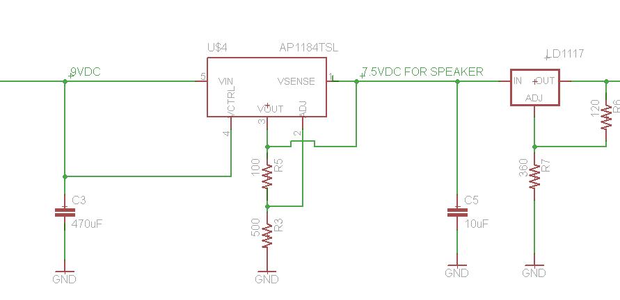
As long as I'm talking about the power circuit, how hot is too hot? I have a heat sink on my 12V regulator and it still gets too hot to touch comfortably.
Thanks!!!
Nora |
|
|
temtronic
Joined: 01 Jul 2010
Posts: 9641
Location: Greensville,Ontario
|
|
| Posted: Tue Jul 26, 2011 5:24 pm |
|
|
You probably need bigger caps in the power supply.
I'd have 10,000 mfd as the primary filter on the +12, 5,000mfd on the +7.5( you show 10mfd), and 1,000 for the +5 to the PIC.
I may get 'scolded' for being 'overkill' but you MUST have a solid,smooth power supply especially when switching relays.They have huge demands for energy (though for a small time ) and a 10 mfd cap just won't do.
If you have an oscilloscope monitor the +5 line and see what happend when the relay turns on. |
|
|
Nora
Joined: 23 Mar 2008
Posts: 50
|
|
| Posted: Tue Jul 26, 2011 5:51 pm |
|
|
temtronic
That worked. I would never have figured that out. I didn't have a 5,000mcf, but I put a 1,000mcf in there (on the 7.5 supply) and my speaker switches.
So big thanks to you!
Will do as you suggested to the rest of the power supply circuit too!
Nora |
|
|
temtronic
Joined: 01 Jul 2010
Posts: 9641
Location: Greensville,Ontario
|
|
| Posted: Wed Jul 27, 2011 7:08 am |
|
|
It's an easy mistake to make when you consider how little power a PIC needs, you can forget about the rest of the circuit ! LEDs, relays,other chips,especially motor drivers all take power.
An easy power supply rule is 1,000mfd filter cap for every 1 amp of current.I treat it as the minimum and use 10,000 for all my bench powered projects( have lots of that cap in stock), never have had a power supply problem in 35 years of doing it this way.
Glad you're 'up and running'! |
|
|
Nora
Joined: 23 Mar 2008
Posts: 50
|
|
| Posted: Sat Jul 30, 2011 10:13 am |
|
|
Hello and Happy Saturday!
I have a couple more power supply questions.
Here is the complete schematic:
http://mix-engineering.com/wp-content/uploads/2011/07/HeartBeat-Dome2.pdf
1. I am running the fan (12V, 36W specc'd, have not measured amps) off 12V, which originates at a car battery (says 100Ah). When I run the fan for awhile, the AP1184TS http://www.diodes.com/datasheets/AP1184.pdf (heatsinked, specc'd at 4A capacity) gets REALLY hot.
When I don't run the fan, it is hot, but "normal" hot.
Since I designed the power supply to start drawing power on the 7.5 V rung, I wouldn't think that the 12V fan would have anything to do with the AP1184TS. The 7.5 V feeds a speaker, which is 7.5V, 2A specc'd but is more like 400mA at most measured.
?
2. When I switch on the 7.5V speaker, it triggers the LEDs ON for a brief moment. I can't tell if this is on the PIC IO line (CCP1 or C2) or if this is a 12V power surge coming back through the line. The LEDs are being driven with a BUCKPLUS 7021-D-E-700 (12V, 700mA).
BTW I highly recommend this driver. It is easy to hook up and doesn't get hot.
Thanks in advance!
Nora |
|
|
|
|
You cannot post new topics in this forum
You cannot reply to topics in this forum
You cannot edit your posts in this forum
You cannot delete your posts in this forum
You cannot vote in polls in this forum
|
Powered by phpBB © 2001, 2005 phpBB Group
|

