 |
 |
| View previous topic :: View next topic |
| Author |
Message |
Fruppy
Joined: 27 May 2021
Posts: 5


|
| Encoder motor control |
 Posted: Thu May 27, 2021 4:08 pm Posted: Thu May 27, 2021 4:08 pm |
 |
|
Hi everyone. I have a problem. I wanna find angle but I couldn't find.
I don't know where is my mistakes. I need help. My code are below:
| Code: |
#include <16F877A.h>
#device adc=10 //set the bit value of adc
#FUSES XT, NOWDT, NOPROTECT, NOBROWNOUT, NOLVP, NOPUT, NODEBUG, NOCPD
#use delay(crystal=4000000)
#include <lcd.c>
#INT_RB // RB port interrupt on change
int8 last_read;
int8 quad;
void RB_IOC_ISR(void)
{
int8 encoderRead;
clear_interrupt(INT_RB);
encoderRead = input_b() & 0x30;
if(encoderRead == last_read)
return;
if(bit_test(encoderRead, 4) == bit_test(last_read, 5))
quad -= 1;
else
quad += 1;
last_read = encoderRead;
}
signed long EncoderGet(void)
{
signed long value = 0;
while(quad >= 4){
value += 1;
quad -= 4;
}
while(quad <= -4){
value -= 1;
quad += 4;
}
return value;
}
unsigned long change = 0;
unsigned long realPosition = 0;
unsigned long angle = 0.0f;
void main()
{
unsigned long int8 pwm;
unsigned int16 rev;
unsigned long int16 referance; //variable for ADC reading value from AN0
unsigned int16 kp; //variable for ADC reading value from AN1
lcd_init();
delay_ms(10);
set_tris_c(0x00); //set all portb pins as output
setup_ccp1(CCP_PWM); //4kHz PWM signal output at CCP1 pin 17
setup_ccp2(CCP_PWM); //4kHz PWM signal output at CCP2 pin 16
setup_timer_2(T2_DIV_BY_16, 255, 1);
setup_adc_ports(ALL_ANALOG); //A0A1 A2 A3 A5 E0 E1 E2 analog pins
setup_adc(ADC_CLOCK_DIV_32); //enable ADC and set clock FOR ADC
while(true)
{
set_adc_channel(0); // next analog reading will be from channel 0
delay_us(10); //allow time after channel selection and reading
referance= read_adc(); //start and read A/D
referance= referance*250;
referance= referance/1023;
referance= referance+20;
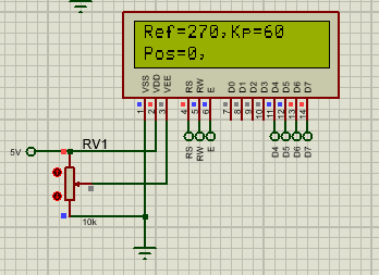
printf(LCD_PUTC,"\fRef=%lu,",referance); //print ADC value FOR A0
set_adc_channel(1); // next analog reading will be from channel 1
delay_us(10); //allow time after channel selection and reading
kp = 50+(read_adc()*10/1023); //start and read A/D
printf(LCD_PUTC,"Kp=%lu",kp); //print ADC value FOR A1
delay_ms(200);
change = EncoderGet();
if(change)
{
realPosition += change;
}
rev = realPosition/360.0f; // Here 360 represents the encoder pulses per revolution
angle = ((int16)(rev*360))%360; // Real time angle is determined in this line
printf(LCD_PUTC,"\nPos=%lu,",angle);
delay_ms(700);
pwm= kp*(referance-angle);
set_pwm1_duty(pwm); //set pulse-width during which signal is high
printf(LCD_PUTC,"Pwm=%lu",pwm);
delay_ms(700);
}
} |
|
|
 |
PCM programmer
Joined: 06 Sep 2003
Posts: 21708
|
| Re: Encoder motor control |
| Posted: Thu May 27, 2021 4:30 pm |
|
|
Make the changes shown in bold below.
| Fruppy wrote: |
#include <16F877A.h>
#device adc=10 //set the bit value of adc
#FUSES XT, NOWDT, NOPROTECT, NOBROWNOUT, NOLVP, NOPUT, NODEBUG, NOCPD
#use delay(crystal=4000000)
#include <lcd.c>
#INT_RB // Wrong location for this line
int8 last_read;
int8 quad;
#INT_RB // Move it to here
void RB_IOC_ISR(void)
{
int8 encoderRead;
clear_interrupt(INT_RB); // This line is not needed.
encoderRead = input_b() & 0x30;
if(encoderRead == last_read)
return;
if(bit_test(encoderRead, 4) == bit_test(last_read, 5))
quad -= 1;
else
quad += 1;
last_read = encoderRead;
}
void main()
{
unsigned int8 temp;
unsigned long int8 pwm;
unsigned int16 rev;
unsigned long int16 referance; //variable for ADC reading value from AN0
unsigned int16 kp; //variable for ADC reading value from AN1
lcd_init();
delay_ms(10);
set_tris_c(0x00); //set all portb pins as output. Your comment does not match the port
temp = input_b(); // Add these 4 lines
enable_interrupts(INT_RB);
clear_interrupt(INT_RB);
enable_interrupts(GLOBAL);
setup_ccp1(CCP_PWM); //4kHz PWM signal output at CCP1 pin 17
setup_ccp2(CCP_PWM); //4kHz PWM signal output at CCP2 pin 16
|
Additional changes may be needed if you are using PortB for
anything other than the two interrrupt on change pins. |
|
|
Fruppy
Joined: 27 May 2021
Posts: 5
|
|
| Posted: Fri May 28, 2021 3:51 am |
|
|
Nothing has changed. The position is always 0. It should normally approach and equalize the reference value.
 |
|
|
temtronic
Joined: 01 Jul 2010
Posts: 9646
Location: Greensville,Ontario
|
|
| Posted: Fri May 28, 2021 4:21 am |
|
|
Is this real hardware or a simulation ?
Print out every intermediate calculation to be 100% sure you don't have a 'math' or 'casting' error.
Use scaled integers instead of floating point. S-Int are more accurate and 10-20x faster.
Last edited by temtronic on Fri May 28, 2021 4:31 am; edited 1 time in total |
|
|
Fruppy
Joined: 27 May 2021
Posts: 5
|
|
| Posted: Fri May 28, 2021 4:26 am |
|
|
| It is a simulation. |
|
|
temtronic
Joined: 01 Jul 2010
Posts: 9646
Location: Greensville,Ontario
|
|
| Posted: Fri May 28, 2021 4:36 am |
|
|
please read PIC101...
It is very well known that Proteus does NOT function 100% ! Even the simplest 'schematic' will NOT work as drawn, in the 'real World'.
I do KNOW that an 877 does run PID controller very, very well. Had real helicopters with 3 axis, 1024 encoders and servo motor in them 20 years ago. |
|
|
Fruppy
Joined: 27 May 2021
Posts: 5
|
|
| Posted: Fri May 28, 2021 4:46 am |
|
|
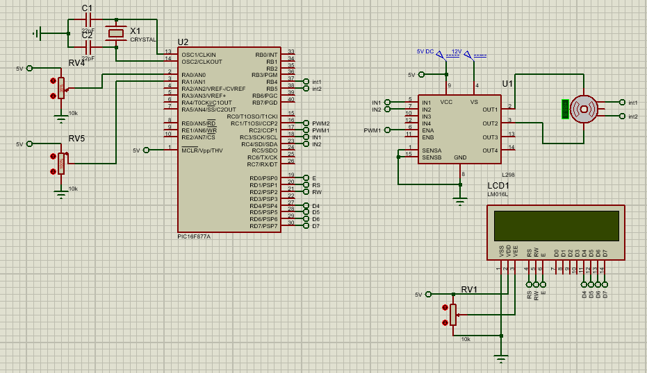
This is my project. I used 877.
The circuit is as in the picture below:
 |
|
|
PCM programmer
Joined: 06 Sep 2003
Posts: 21708
|
|
| Posted: Fri May 28, 2021 8:06 am |
|
|
Post your latest program so we can see if you made the changes.
Also, why are you mixing data types as shown below in bold ?
| Quote: | unsigned long int8 pwm;
unsigned int16 rev;
unsigned long int16 referance;
unsigned int16 kp;
|
A 'long int8' is the same as int16, so why not just use int16 ?
A 'long int16' is the same as int32, so why not just use int32 ? |
|
|
Fruppy
Joined: 27 May 2021
Posts: 5
|
|
| Posted: Fri May 28, 2021 8:40 am |
|
|
I'm new to coding, so I didn't know that long int16 and int32 mean the same thing. Code is below
| Code: |
#include <16F877A.h>
#device adc=10 //set the bit value of adc
#FUSES XT, NOWDT, NOPROTECT, NOBROWNOUT, NOLVP, NOPUT, NODEBUG, NOCPD
#use delay(crystal=4000000)
#include <lcd.c>
int8 last_read;
int8 quad;
#INT_RB // RB port interrupt on change
void RB_IOC_ISR(void)
{
int8 encoderRead;
encoderRead = input_b() & 0x30;
if(encoderRead == last_read)
return;
if(bit_test(encoderRead, 4) == bit_test(last_read, 5))
quad -= 1;
else
quad += 1;
last_read = encoderRead;
}
signed long EncoderGet(void)
{
signed long value = 0;
while(quad >= 4){
value += 1;
quad -= 4;
}
while(quad <= -4){
value -= 1;
quad += 4;
}
return value;
}
unsigned long change = 0;
unsigned long realPosition = 0;
unsigned long angle = 0.0f;
void main()
{
unsigned int8 temp;
unsigned int16 pwm;
unsigned int16 rev;
unsigned int32 referance; //variable for ADC reading value from AN0
unsigned int16 kp; //variable for ADC reading value from AN1
lcd_init();
delay_ms(10);
set_tris_c(0x00); //set all portc pins as output
temp = input_b();
enable_interrupts(INT_RB);
clear_interrupt(INT_RB);
enable_interrupts(GLOBAL);
setup_ccp1(CCP_PWM); //4kHz PWM signal output at CCP1 pin 17
setup_ccp2(CCP_PWM); //4kHz PWM signal output at CCP2 pin 16
setup_timer_2(T2_DIV_BY_16, 255, 1);
setup_adc_ports(ALL_ANALOG); //A0A1 A2 A3 A5 E0 E1 E2 analog pins
setup_adc(ADC_CLOCK_DIV_32); //enable ADC and set clock FOR ADC
while(true)
{
set_adc_channel(0); // next analog reading will be from channel 0
delay_us(10); //allow time after channel selection and reading
referance= read_adc(); //start and read A/D
referance= referance*250;
referance= referance/1023;
referance= referance+20;
printf(LCD_PUTC,"\fRef=%lu,",referance); //print ADC value FOR A0
set_adc_channel(1); // next analog reading will be from channel 1
delay_us(10); //allow time after channel selection and reading
kp = 50+(read_adc()*10/1023); //start and read A/D
printf(LCD_PUTC,"Kp=%lu",kp); //print ADC value FOR A1
delay_ms(200);
change = EncoderGet();
if(change)
{
realPosition += change;
}
rev = realPosition/360.0f; // Here 360 represents the encoder pulses per revolution
angle = ((int16)(rev*360))%360; // Real time angle is determined in this line
printf(LCD_PUTC,"\nPos=%lu,",angle);
delay_ms(700);
pwm = kp*(referance-angle);
set_pwm1_duty(pwm); //set pulse-width during which signal is high
if(pwm>1023){
pwm=1023;
}
if(pwm<0){
pwm=0;
}
printf(LCD_PUTC,"Pwm=%lu",pwm);
delay_ms(700);
}
}
|
|
|
|
PCM programmer
Joined: 06 Sep 2003
Posts: 21708
|
|
| Posted: Fri May 28, 2021 5:50 pm |
|
|
A few more problems:
| Fruppy wrote: |
#use delay(crystal=4000000)
setup_adc(ADC_CLOCK_DIV_32);
while(true)
{
set_adc_channel(0);
delay_us(10); // Should be 20 usec delay
set_adc_channel(1);
delay_us(10); // Should be 20 usec delay
|
The 16F877A data sheet says that for a 4 MHz PIC oscillator
frequency, the ADC clock divisor should be 8. Change the
setup_adc() statement to be:
| Code: |
setup_adc(ADC_CLOCK_DIV_8);
|
The data sheet also says the ADC acquisition time is 19.72 us.
You should change each of the delay_us(10) statements to be:
I compiled your latest program. I got these warnings:
| Quote: | >>> Warning 204 Line 30(1,1): Condition always FALSE
>>> Warning 205 Line 90(1,1): Unsigned variable is never less than zero
>>> Warning 204 Line 90(1,1): Condition always FALSE
|
You need to fix these problems. |
|
|
temtronic
Joined: 01 Jul 2010
Posts: 9646
Location: Greensville,Ontario
|
|
| Posted: Sat May 29, 2021 6:45 am |
|
|
I don't see any control over IN1,IN2 of the L298 so there's NO directional control, possibly the motor won't spin....
Also since PWM register is just 0-1023, you don't need signed values to control it( the 'math' ) |
|
|
|
|
You cannot post new topics in this forum
You cannot reply to topics in this forum
You cannot edit your posts in this forum
You cannot delete your posts in this forum
You cannot vote in polls in this forum
|
Powered by phpBB © 2001, 2005 phpBB Group
|

