| View previous topic :: View next topic |
| Author |
Message |
georpo
Joined: 18 Nov 2008
Posts: 281
Location: Athens, Greece.


|
| ACS758LCB-100U AC current. |
 Posted: Tue Mar 30, 2021 1:55 am Posted: Tue Mar 30, 2021 1:55 am |
 |
|
Hello!
I am using the ACS758LCB-100U to measure mains AC current in the range of 10-50A. The ACS758 is supplied with 5V and I scale it down to 3.3V with a 8K2/10K resistor divider.
The ACS758LCB-100U has a zero current offset of 0.6V and 40mV/A and will give me values for half the AC cycle.
What is the correct way to measure current?
Thanks!
_________________
George. |
|
 |
Ttelmah
Joined: 11 Mar 2010
Posts: 20056
|
|
| Posted: Tue Mar 30, 2021 2:27 am |
|
|
First get rid of the resistive divider....
Now you don't tell us 'what PIC', but a lot of the 3.3v PIC's require
quite a low impedance drive for their ADC's. The divider may well cause
issues. If you are running the PIC at 3.3v, then run the ACS from the same
voltage. It supports operation down to 3v.
Honestly if you are measuring AC current, then use the B version, not the
U version. Unless you add a protection diode to stop the reverse half cycles
actually passing through the sensor, the input amplifier will be overloaded
on the reverse half cycles, and will result in significant errors.
The DC sensor is not rated for use on AC.
Add a small amount of AC filtering to reduce HF spikes, and then simply read
the voltage. It is linearly proportional to current from the nominal zero
point to full scale. |
|
|
alan
Joined: 12 Nov 2012
Posts: 358
Location: South Africa
|
|
| Posted: Tue Mar 30, 2021 2:30 am |
|
|
I use these current sensors and although they spec that they work down to 3V, I could never get them to be reasonable accurate at that supply voltage. What worked for me are a buffer and then the divider.
Regards |
|
|
georpo
Joined: 18 Nov 2008
Posts: 281
Location: Athens, Greece.
|
|
| Posted: Tue Mar 30, 2021 2:37 am |
|
|
PIC is a PIC24FJ128GA308.
Yes, the ACS operates down to 3v but it is stated in the pdf that:
| Quote: |
[1] Device is factory-trimmed at 5 V, for optimal accuracy.
[2] Devices are programmed for maximum accuracy at 5.0 V VCC levels. The device contains ratiometry circuits that accurately alter the 0 A Output Voltage and Sensitivity
level of the device in proportion to the applied VCC level. However, as a result of minor nonlinearities in the ratiometry circuit additional output error will result when VCC
varies from the 5 V VCC level. Customers that plan to operate the device from a 3.3 V regulated supply should contact their local Allegro sales representative regarding
expected device accuracy levels under these bias conditions.
|
I did not like the " contact their local Allegro sales representative" and decided to go for 5V.
There is also a 100n ceramic cap parallel to the 10K resistor.
As about the reading, I think it is not that simple.
Shouldn't I take reading for a full half cycle 10mS and find the peak value?
Or sum the square of the values and then divide the average by sqrt(2)?
I have tried various methods but the current reading is not correct.
Any code guidelines?
I will indeed change to the B version though.
_________________
George. |
|
|
temtronic
Joined: 01 Jul 2010
Posts: 9631
Location: Greensville,Ontario
|
|
| Posted: Tue Mar 30, 2021 5:30 am |
|
|
random comments....
1 ) be sure to install with a BIG heatsink ! Check the datasheet.there's a dwg with dimns...go bigger...cooler it runs the better.
2) how to measure, depends on the 'type' of current you want to know about. RMS, instaneous, etc.
2a) forget about floating point ! Use scaled integers to do all the math ! 10 - 50x FASTER AND more accurate.
2b) consider using a zero cross detector to KNOW where the cycle begins and ends
3) perhaps buy a premade 'module'. Costs less than 'all the parts' and the 'front end' AC to DC is already done. Typically '0' is -veA, 2.5 is0A, +5 is +ve A. |
|
|
Ttelmah
Joined: 11 Mar 2010
Posts: 20056
|
|
| Posted: Tue Mar 30, 2021 6:46 am |
|
|
OK. Use 5v, but in which case on most 3.3v PIC's you need a buffer amplifier.
Problem is that the unit only 'just' has a low enough output impedance to
feed a traditional PIC ADC. Any of the modern PIC's with high speed ADC's
have much lower input impedance's. If you look at chips like the PIC33's,
figures like 100R!... Even most of the faster PIC16/18's, the impedances
required are down at just 2.5KR. The chip just cannot feed that and give
good accuracy...
However I have to repeat the issue with using the DC module on AC. It
causes the amplifier to saturate, and for several mSec after the transition
to +ve you get incorrect results. |
|
|
georpo
Joined: 18 Nov 2008
Posts: 281
Location: Athens, Greece.
|
|
| Posted: Thu Apr 01, 2021 6:34 am |
|
|
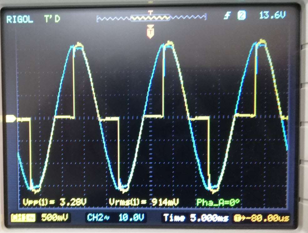
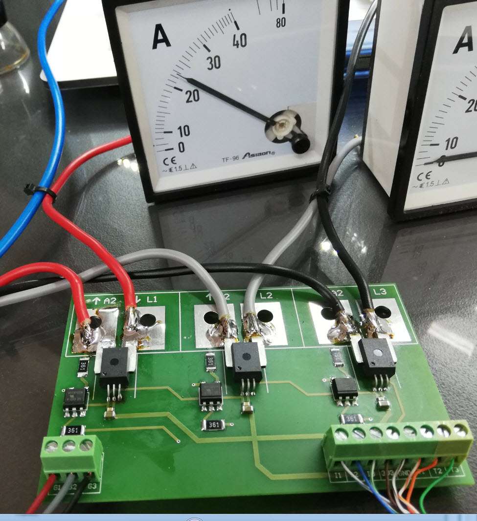
OK, I used the 'B' version.
I measure p-p voltage, calculate RMS voltage and then current.
My serial terminal matches the analog Ammeter. Success!
But there is a problem.
The PIC24 is used here to control the power of the load.
Of course I have zero cross detection etc, all these work just fine and the Amperes on the analog Ammeter are controlled just fine.
The problem is that the ACS758 does not like the chopped AC and shows error readings.
Any thoughts?
_________________
George. |
|
|
Ttelmah
Joined: 11 Mar 2010
Posts: 20056
|
|
| Posted: Thu Apr 01, 2021 7:21 am |
|
|
That's where an inductor/capacitor filter comes in.
You need that anyway, otherwise the supply may well complain about the
power factor. |
|
|
georpo
Joined: 18 Nov 2008
Posts: 281
Location: Athens, Greece.
|
|
| Posted: Thu Apr 01, 2021 8:18 am |
|
|
Ttelmah please explain about the inductor/capacitor filter.
You mean in line with the load?
_________________
George. |
|
|
Ttelmah
Joined: 11 Mar 2010
Posts: 20056
|
|
| Posted: Thu Apr 01, 2021 8:30 am |
|
|
With correct component selection, an LC filter allows you to convert a
chopped AC waveform into a pure sinusoid. Current measurements on this
then won't have the spike characteristics of the chopper. |
|
|
georpo
Joined: 18 Nov 2008
Posts: 281
Location: Athens, Greece.
|
|
| Posted: Thu Apr 01, 2021 9:10 am |
|
|
You are talking about biiiig inductors. The current in this circuit is about 50A or more.
So there is no way to deal with this in software?
_________________
George. |
|
|
georpo
Joined: 18 Nov 2008
Posts: 281
Location: Athens, Greece.
|
|
| Posted: Fri Apr 02, 2021 3:25 am |
|
|
For anyone in similar case, there are ICs that do the job.
I will try the LTC1968 true RMS-to-DC convertor.
It can convert a distorted, chopped etc signal to DC.
I was just hoping for a software solution.
Thanks.
_________________
George. |
|
|
temtronic
Joined: 01 Jul 2010
Posts: 9631
Location: Greensville,Ontario
|
|
| Posted: Fri Apr 02, 2021 4:53 am |
|
|
There are software solutions, all require a very fast and powerful micro, dedicated to that one task of 'cleaning up' the signal. These days a 'DSP' style micro, running flat out, could probably deconstruct the 'dirty' signal and present a 'clean' signal to the PIC.
You already have, what we don't know, the PWM frequency, the specs of the motor controller (interface module) and the motor.
Given those either a simple L-C, or even an L-C-L-C filter might 'cleanup' the signal enough for the PIC ADC to give reliable readings.
Big issue to me is the 50A current. That requires big, fat, traces and wires, perfect grounds and lots of bypass caps. Ferrite chokes will help. In my previous life, I made 32 channel, 16 bit ADC front-ends for optical emission spectrometers (steel sparkers, 100s of ma at 1,000s of volts). Could get 15 usable bits out of 16. |
|
|
georpo
Joined: 18 Nov 2008
Posts: 281
Location: Athens, Greece.
|
|
| Posted: Fri Apr 02, 2021 5:08 am |
|
|
I think that the task is not to clean up the signal.
The ACS758 does not like the chopped waveform and starts giving errors at about 90 degrees firing angle of the triac.
The "interface module" is just a triac BTA40-700.
The load is resistive.
The LTC1968 is supposed to do the magic. I will have to wait for the part to arrive.
In the meanwhile, any thoughts are welcome.
_________________
George. |
|
|
Woody
Joined: 11 Sep 2003
Posts: 86
Location: Warmenhuizen - NL
|
|
| Posted: Fri Apr 02, 2021 7:26 am |
|
|
Maybe too little too late, but I once used Temtronics' suggestion of using a zero-cross circuit. After the zero cross I waited 5 ms and did an AD conversion (of an ACS712) to obtain the peak current. Then some averaging.
Iirc that worked quite nicely, as long as the power factor was not too bad.
The only real problem I ran into was with a relay next to the ACS; as soon as the relay was activated its magnetic field mucked up the reading from the (Hall based) current sensor. |
|
|
|


