| View previous topic :: View next topic |
| Author |
Message |
flyboy71
Joined: 14 Mar 2019
Posts: 8


|
| CCPx accuracy as a one shot |
 Posted: Thu Mar 14, 2019 7:28 am Posted: Thu Mar 14, 2019 7:28 am |
 |
|
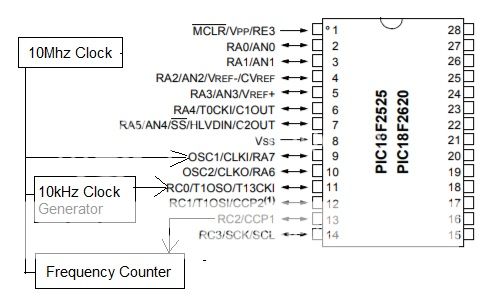
First time posting on here but I'm finding little on this subject. Using code from the examples I am attempting a 1 second one shot using CCP compare to generate a precise one second output. The osc clock to the PIC is from a 10MHz frequency standard, the external input to Timer 1 is 10kHz which is locked to the 10Mhz standard and the time interval counter I am using to measure the time is locked to the same 10MHz standard.
With CCP1 set to 10000 the result is 0.9999845
With CCP1 set to 10001 the result is 1.0000845
Sometimes it's not 845, sometimes its 537 or 746 or another number. So I can't adjust for it. So I can't get an exact 1 second even and it appears the difference from 1 second is half a clock cycle of the 10kHz input. This would suggest its starting on a rising edge and stopping on a falling edge or vice versa.
Where this is important is that I am using this pulse to count 10MHz clocks using an external counter and this offset equates to hundreds of Hz of error at 10MHz.
Obviously this isn't strictly hardware driven or the timer would begin and end at exactly 10000 counts. So what is really going on that is hardware and what part of this is coming from software? Is there another way to do this that is hardware only using the PIC? Am I asking too much of the device?
On a secondary issue: Using TI_EXTERNAL does not function for some reason so I can't un-sync the external clock to see if that makes a difference.
Device I'm using is an 18F2525 Here is the code:
| Code: |
#include <18F2525.h>
#device ADC=16
#FUSES NOWDT //No Watch Dog Timer
#FUSES WDT128 //Watch Dog Timer uses 1:128 Postscale
#FUSES NOBROWNOUT //No brownout reset
#FUSES NOLVP //No low voltage prgming, B3(PIC16) or B5(PIC18) used for I/O
#FUSES NOXINST //Extended set extension and Indexed Addressing mode disabled (Legacy mode)
#FUSES EC
#use delay(clock=10MHz)
|
| Code: | #include <main.h>
void main()
{
setup_timer_1(T1_DIV_BY_1);
setup_timer_1(T1_EXTERNAL_SYNC);
while(TRUE)
{
setup_ccp1(CCP_COMPARE_SET_ON_MATCH);
ccp_1 = 0;
set_timer1(0);
ccp_1 = 10001;
setup_ccp1(CCP_COMPARE_CLR_ON_MATCH);
while(input_state(PIN_C2)); //read pin state and wait till done
delay_ms(100);
}
}
|
|
|
 |
temtronic
Joined: 01 Jul 2010
Posts: 9641
Location: Greensville,Ontario
|
|
| Posted: Thu Mar 14, 2019 7:37 am |
|
|
quick comment...
for super accurate timings, you should always use a crystal that is 'binary' in cut. Something that is divisible by 2. Watch xtals are, 32,768 KHzis a nice cut, so is a 2.457600 MHz xtal.
using a 'binary' xtal you eliminate the error within the 'math'. |
|
|
flyboy71
Joined: 14 Mar 2019
Posts: 8
|
|
| Posted: Thu Mar 14, 2019 8:14 am |
|
|
I could use a binary frequency but I'm unsure how that affects the result being my measured input is external to Timer1 unless the error I am seeing is due to instruction clocks and how this is handled. That's the part I'm unsure of since everything outside the PIC is synchronized to a reference.
My next step is to use a scope to trigger on the CCP pin and see how it aligns to edges of the 10kHz clock. I'm guessing there will be a delay between the two that adds to half a clock or so. In the intended application the 10kHz input will vary slightly in frequency and that variation will change the pulse width which will be measured to correct it back to 10kHz. So if my counts have error with a fixed frequency in this setup then this will never work to measure variation to any accuracy.
Here is the setup. The HP frequency counter is set to measure positive pulse width out to 8 decimal place precision:
 |
|
|
Ttelmah
Joined: 11 Mar 2010
Posts: 20093
|
|
| Posted: Thu Mar 14, 2019 9:17 am |
|
|
Some comments:
| Code: |
#use FAST_IO C
void main()
{
setup_timer_1(T1_DIV_BY_1 | T1_EXTERNAL_SYNC);
//timer settings need to be done in one line, not one after
//the other
output_drive(PIN_C2); //set TRIS to output on C2
ccp_1 = 10001; //preload the CCP
setup_ccp1(CCP_COMPARE_CLR_ON_MATCH); //set the operation
while(TRUE)
{
set_timer1(0); //clear the timer
output_high(PIN_C2); //set pin high
//The CCP will now clear this when the count reaches 10001
while(input_state(PIN_C2))
; //read pin state and wait till done
//You will reach this point four instruction times after the total
//count. One is the time for the output instruction. Two are the
//time for the test on the pin. The final one is the advance to this
//point.
delay_ms(100);
}
}
|
Now (obviously), with the count being asynchronous to the CPU, there
can be up to one whole cycle of the external clock difference in when
the count will actually be reached. If you want an exact 1 second, then
better to actually use the processor clock rather than an external source. |
|
|
flyboy71
Joined: 14 Mar 2019
Posts: 8
|
|
| Posted: Thu Mar 14, 2019 10:26 am |
|
|
Based on the comments in the code you may have answered my question. Even though the schematic representation in the datasheet shows what looks like hardware logic, the processor actually uses instructions to see a match then set the pin, whereas if it was all hardware the pin would change at the moment the counter reached the final edge and was matched. That of course and other instruction cycles to process what to do and actually do it. I originally was going the route of doing a compare at say 55535 set the pin and then an interrupt on overflow and reset the pin but the interrupt handler would have delayed this much further I believe.
Unfortunately in this application I need to count the external 10kHz so I may just go with an external hardware counter in an FPGA or similar to make the pulse and handle the other logic. At least I connected this and did a baseline before going any further with it and learned something in the process. |
|
|
Ttelmah
Joined: 11 Mar 2010
Posts: 20093
|
|
| Posted: Thu Mar 14, 2019 1:39 pm |
|
|
No.
The actual edge will occur when the CCP _hardware_ triggers.
However you have to remember you are clocking the CCP from
an external clock. The processor _starts_ the pulse at a point in
time based on it's clock. This can be at any point in the cycle of the
external clock. Result variation in the pulse.
You seem to possibly try to trigger the other edge from the hardware,
but you are not letting this actually happen, so the start is dependant
on the processor clock not your external source.
Re-code the starting edge to use the same technique, and then the
edges will be synchronous to the external clock. |
|
|
flyboy71
Joined: 14 Mar 2019
Posts: 8
|
|
| Posted: Thu Mar 14, 2019 6:11 pm |
|
|
| So I went back and made some code changes to what you had posted and was still getting the variation. I decided to put my dual channel scope on the CCPx and 10kHz clock and trigger on the CCPx using a single sweep. As expected the CCP pin went high about 18us after the rising edge of the clock and CCP went low about 540ns after the rising edge of the clock at the actual count. So the ultimate solution was to use a D-flip-flop with the D input tied to CCP and the clock input tied to the 10kHz clock. When CCP goes high its state appears on the output Q on the next rising edge of clock until CCP goes low and the N+1 rising edge is seen on clk. With a count of 10000 the pulse width is now a perfect 1.0000000 seconds and holds perfectly steady. 2000 gives 200ms and 20000 gives exactly 2 seconds. I can easily add a single small D-flip-flop to the design. So it is possible to get precise timing with a little help from some hardware. |
|
|
|


