| View previous topic :: View next topic |
| Author |
Message |
carllw
Joined: 22 Feb 2018
Posts: 10


|
| MQ-2 and PIR sensors interfacing with PIC |
 Posted: Sat May 19, 2018 12:34 am Posted: Sat May 19, 2018 12:34 am |
 |
|
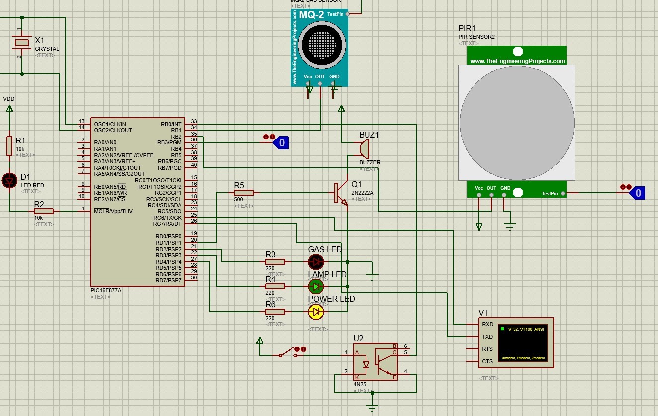
Hi, I have a problem about my circuit. I created circuit below and code is here but there is a problem. There is an IR Sensor to detect car is on garage or not (parking lot is full or empty). If you exit from home, lot data return from full to empty. At this time if user forgot gas opened at home, user take a warning message like Gas opened or Pir sensor detects thief then send message There is a thief etc. This is what i want to do. I created all hardware but there is a problem. Every time parking lot return from full to empty system gives me message independent from lighter is used or not. How can i fix it ? Thanks.
I used mq-2 sensor module
IR Sensor module to detect parking lot on pin no 36
and message is sent by using espp8266 to mobile app.
| Code: | #include<16F877A.h>
#fuses HS
#use delay (clock=20000000)
#use rs232 (baud=115200,xmit=pin_c6,rcv=pin_c7)
//ALL PINS
//PIN A0,A1,A2,A3 are input
//PIN D2,D3 are output for LEDs
//PIN D1 is output for buzzer
//PIN B2 input for pir sensor
//PIN B0 is input for lamp detection
//PIN B1 is input for Gas sensor if digital(only true for proteus simulation)
int16 adc_value0,adc_value1,adc_value2,adc_value3;
float volts;
void main(void)
{
//set port D as output
set_tris_b(0xff);
set_tris_d(0x00);
output_d(0x00);
port_b_pullups(TRUE);
setup_comparator(NC_NC_NC_NC);
setup_port_a(ALL_ANALOG);
setup_adc(ADC_CLOCK_INTERNAL);
printf("\HI");
delay_ms(1000);
printf("AT\r\n");
delay_ms(250);
printf("AT+RST\r\n");
delay_ms(3000);
printf("AT+CWMODE=3\r\n");//3
delay_ms(3000);
printf("AT+CWSAP=\"car_parking\",\"12345678\",7,4\r\n");
delay_ms(5000);
printf("AT+CIPMUX=1\r\n");
delay_ms(4000);
printf("AT+CIPSERVER=1\r\n");
delay_ms(4000);
while(1)
{
set_adc_channel(0); // Select channel 0 input
delay_ms(100);
adc_value0 = read_adc(); //get 10 bit readig for channel 0
// Configure RA0 (AN0) as analog
set_adc_channel(1); // Select channel 0 input
delay_ms(100);
adc_value1 = read_adc(); //get 10 bit readig for channel 0
// Configure RA0 (AN0) as analog
set_adc_channel(2); // Select channel 0 input
delay_ms(100);
delay_us(20);
adc_value2 = read_adc();
set_adc_channel(3);
delay_ms(100);
adc_value3 = read_adc();
//get 10 bit readig for channel 0
output_high(PIN_D4);
if(adc_value0<=200)
{
printf("AT+CIPSEND=0,12\r\n");
delay_ms(100);
printf("zone1,full ");
delay_ms(100);
}
else
{
printf("AT+CIPSEND=0,13\r\n");
delay_ms(100);
printf("zone1,empty ");
delay_ms(100);
if(adc_value3<=500) //gas detection code
{
printf("AT+CIPSEND=0,22\r\n");
delay_ms(100);
printf("DANGER!!!,GAS IS ON ");
delay_ms(100);
output_high(PIN_D2);
delay_ms(2000);
}
if(input_state(PIN_B0)==0) // lamp detection code
{
printf("AT+CIPSEND=0,13\r\n");
delay_ms(100);
printf("LAMP IS ON ");
delay_ms(100);
output_high(PIN_D3);
delay_ms(2000);
}
if(input_state(PIN_B2)==1) // pir sensor code
{
printf("AT+CIPSEND=0,27\r\n");
delay_ms(100);
printf("DANGER!!!,THEIF DETECTED ");
delay_ms(100);
output_high(PIN_D1); //buzzer is attached to pin D1
delay_ms(4000);
}
}
output_low(PIN_D1); //output for buzzer
output_low(PIN_D3); //led for lamp detection
output_low(PIN_D2);
output_high(PIN_D4);
delay_ms(2000);
}
}
|
[/img] |
|
 |
PCM programmer
Joined: 06 Sep 2003
Posts: 21708
|
|
| Posted: Sat May 19, 2018 1:35 am |
|
|
Your code expects the adc to be in 10-bit mode. But it's not, because the
default mode is 8-bit.
To put the adc in 10-bit mode, add the line shown below in bold:
| Quote: |
#include<16F877A.h>
#device adc=10
#fuses HS
#use delay (clock=20000000)
|
|
|
|
carllw
Joined: 22 Feb 2018
Posts: 10
|
| MQ-2 and PIR sensors interfacing with PIC |
| Posted: Sat May 19, 2018 1:51 am |
|
|
| PCM programmer wrote: | Your code expects the adc to be in 10-bit mode. But it's not, because the
default mode is 8-bit.
To put the adc in 10-bit mode, add the line shown below in bold:
| Quote: |
#include<16F877A.h>
#device adc=10
#fuses HS
#use delay (clock=20000000)
|
|
Sir really thanks, now i take clearly data from PIR but now gas sensor gives nothing. I connect A0 pin of mq-2 to pin 34 and D0 is empty. How can i fix it ? Code or hardware is problem ? And for 4n25 circuit, when i connect pin1 of 4n25 to 5v, circuit closed, i used ltv4n25. |
|
|
temtronic
Joined: 01 Jul 2010
Posts: 9632
Location: Greensville,Ontario
|
|
| Posted: Sat May 19, 2018 4:48 am |
|
|
some general comments...
This line of code...
setup_adc(ADC_CLOCK_INTERNAL);
is incorrect.
For most PICs it's ONLY used when the CPU clock is 1MHz or lower and when the PIC is asleep. There is a chart of adc clcok options int eh ADC section of the datasheet. While you _can_ use it, the ADC is not goin gto perform properly, giving either bad or random readings.
is the 'buzzer' electromechanical or piezo style? If electromechanical, they generte a lot of EMI (noise) and could be resetting ot altering the PIC.
You talk about a 4N25, besure to have the correct curent limiting resistor on the diode side and a 4k7 pullup on the transistor side. |
|
|
carllw
Joined: 22 Feb 2018
Posts: 10
|
|
| Posted: Sat May 19, 2018 5:44 am |
|
|
| temtronic wrote: | some general comments...
This line of code...
setup_adc(ADC_CLOCK_INTERNAL);
is incorrect.
For most PICs it's ONLY used when the CPU clock is 1MHz or lower and when the PIC is asleep. There is a chart of adc clcok options int eh ADC section of the datasheet. While you _can_ use it, the ADC is not goin gto perform properly, giving either bad or random readings.
is the 'buzzer' electromechanical or piezo style? If electromechanical, they generte a lot of EMI (noise) and could be resetting ot altering the PIC.
You talk about a 4N25, besure to have the correct curent limiting resistor on the diode side and a 4k7 pullup on the transistor side. |
Thanks sir, i removed buzzer and buzzer led connections. Pull-up resistor works thanks. My only problem is gas sensor now, ı cant take any data from sensor. How can i fix it ? |
|
|
temtronic
Joined: 01 Jul 2010
Posts: 9632
Location: Greensville,Ontario
|
|
| Posted: Sat May 19, 2018 1:21 pm |
|
|
It's best to create a simple 'gas detector' only program.
A basic loop, say once every second to read the sensor and send the raw data to PC or LCD module. Do that, show us the code, then we can help.
It's always best to divide a big program into smaller tasks, get one to work, save, go onto the next one...
Jay |
|
|
PCM programmer
Joined: 06 Sep 2003
Posts: 21708
|
|
|
Ttelmah
Joined: 11 Mar 2010
Posts: 20058
|
|
| Posted: Sun May 20, 2018 2:46 am |
|
|
Before going any further, the MQ2 does not give a voltage out. It needs a resistor from it's output pin to ground to do this. This is normally a pot, so you can set the voltage it gives, since the units vary significantly. It gives a resistance that varies with gas concentration.
It also needs a long time to warm up. The manufacturer recommends letting it stabilse for 24 hours before calibrating.
Then third thing, the output really needs a op-amp buffer to feed a PIC ADC. The MQ2 output resistance at 2000ppm C3H8, varies between 2KR and 20KR according to the example you have. Only the very bottom of this range offers a low enough impedance to safely operate the PIC ADC..... |
|
|
temtronic
Joined: 01 Jul 2010
Posts: 9632
Location: Greensville,Ontario
|
|
| Posted: Sun May 20, 2018 5:30 am |
|
|
Wow, I thought Mr. T had misread the datasheet(unlikely..he has better glasses than me..), so I grabbed one ...YIKES the test data says 48 HRS to stabilize, that's 2 days !! I assume once it's all warmed up, then the 1 DAY is 'nominal'.
Drawing 150ma for the heater also means you need a big power supply,probably not the one the PIC or sensor is attached to as ANY variation would change the sensor's output. Then there's the calibration routine to get the slope...more 'fun'. And each sensor is unique.....
Jay |
|
|
Ttelmah
Joined: 11 Mar 2010
Posts: 20058
|
|
| Posted: Sun May 20, 2018 7:02 am |
|
|
Fortunately the 'uniqueness' can be dealt with by letting the sensor settle, and then setting the pot I mentioned to give a standard output. However it needs pot, and op-amp to feed the ADC of the PIC.
The stabilising time is terrible....  |
|
|
temtronic
Joined: 01 Jul 2010
Posts: 9632
Location: Greensville,Ontario
|
|
| Posted: Sun May 20, 2018 7:14 am |
|
|
but,but ,but...
"After the sensor is powered, needs wait about 20S, measured data was stable, heat sensor is a normal phenomenon, because the internal heating wire." a direct quote from one seller of these units !
I did check the pictures and the MODULE has opamp on it and other SMT 'stuff'. 
Have to admit for $2 CDN it's a great deal, then again I paid north of $10K for my first Personal Computer... 
Jay |
|
|
Ttelmah
Joined: 11 Mar 2010
Posts: 20058
|
|
| Posted: Sun May 20, 2018 7:19 am |
|
|
Module?....
Question is does he just have the MQ2 sensor on a board, or a module with the support circuitry. If the latter he may have the pot and op-amp already.
However 'module' could be either.
Also the stabilising time for an accurate result is presumably very different from the chip's own wakeup time....
Checking the data from the manufacturer's representative, they say the chip should be 'preheated' for at least 24 hours _after storage_. If it has not been powered for a significant time.
For normal operation values should be stable within 30 minutes, but within 10% after only a couple of minutes.
Not quite as bad... 
It does mean that the first use should leave the unit powered for a long time before calibrating. |
|
|
carllw
Joined: 22 Feb 2018
Posts: 10
|
| MQ-2 and PIR sensors interfacing with PIC |
| Posted: Mon May 21, 2018 11:27 am |
|
|
| Thanks for all answers. I corrected code and now all sensors are working. |
|
|
|


