| View previous topic :: View next topic |
| Author |
Message |
maumau.marinho
Joined: 07 Mar 2018
Posts: 3


|
| EEPROM external memory 25LC512 |
 Posted: Wed Mar 07, 2018 8:27 pm Posted: Wed Mar 07, 2018 8:27 pm |
 |
|
Difficult to find the error in the code, it is not writing in 25LC512.
I'm using the pic18f4550 and external memory 25LC512.
I have a problem with my code, because this one is not writing or reading.
| Code: |
#include <18F4550.h>
#use delay (clock=8000000)
#fuses HS, NOWDT, PUT, BROWNOUT, NOLVP, CPUDIV1
#use rs232(baud=9600, xmit = PIN_C6, rcv = PIN_C7)
#define B1 PIN_B0
#define B2 PIN_C0
#define EEPROM_SELECT PIN_A3
#define EEPROM_ADDRESS long int
#define EEPROM_SIZE 32768
void init_ext_eeprom()
{
output_high(EEPROM_SELECT);
setup_spi(SPI_MASTER | SPI_XMIT_L_TO_H | SPI_L_TO_H | SPI_CLK_DIV_4 );
}
int1 ext_eeprom_ready(void)
{
int8 data;
output_low(EEPROM_SELECT);
spi_write(0x05);
data = spi_read(0);
output_high(EEPROM_SELECT);
return(!bit_test(data, 0));
}
void write_ext_eeprom(EEPROM_ADDRESS address, BYTE data)
{
while(!ext_eeprom_ready());
output_low(EEPROM_SELECT);
spi_write(0x06);
output_high(EEPROM_SELECT);
output_low(EEPROM_SELECT);
spi_write(0x02);
spi_write(address >> 8);
spi_write(address);
spi_write(data);
output_high(EEPROM_SELECT);
delay_ms(5);
}
BYTE read_ext_eeprom(EEPROM_ADDRESS address)
{
int8 data;
while(!ext_eeprom_ready());
output_low(EEPROM_SELECT);
spi_write(0x03);
spi_write(address >> 8);
spi_write(address);
data = spi_read(0);
output_high(EEPROM_SELECT);
return(data);
}
void main()
{
int i;
printf("\f DATALOG SUCESSO ");
printf("\nB1:Esc - B2:Ler ");
delay_ms(100);
init_ext_eeprom();
while (true)
{
if (input(B1))
{
write_ext_eeprom(0,'E');
write_ext_eeprom(1,'X');
write_ext_eeprom(2,'I');
write_ext_eeprom(3,'T');
write_ext_eeprom(4,'O');
write_ext_eeprom(5,'S');
printf("\nPress. B2 p/ ler\n");
}
if(input(B2))
{
for (i=0;i<6;i++)
{
printf("%c",read_ext_eeprom(i));
delay_ms(300);
}
}
}
} |
|
|
 |
PCM programmer
Joined: 06 Sep 2003
Posts: 21708
|
|
| Posted: Wed Mar 07, 2018 8:45 pm |
|
|
Post a list of your connections between the 18F4550 and the 25LC512.
You are using hardware SPI, which must use these pins:
C7 = SDO (MOSI)
B0 = SDI (MISO)
B1 = SCK
So you can see that you have a conflict in your pin usage. You are using
pin B0 for one of your buttons, and pin C7 is used by the hardware UART.
It would be better to use software SPI, which you can do with #use spi().
But, we need to know your connections between the PIC and the eeprom. |
|
|
maumau.marinho
Joined: 07 Mar 2018
Posts: 3
|
|
| Posted: Wed Mar 07, 2018 9:18 pm |
|
|
Hi, should not I use B0 pin as input? The C7 pin used does not use rs232 for rcv.
You said that I could add #use spi () syntax can be that way anyway?
was connected in this way
SCK -> RB1
SDi -> RB0
SDO -> RC7 |
|
|
Ttelmah
Joined: 11 Mar 2010
Posts: 20058
|
|
| Posted: Thu Mar 08, 2018 2:38 am |
|
|
If the pin is being used by the SPI, it is being controlled and used by the peripheral. Trying to mix use could damage the chip. Imagine it tries to send data while the pin is being held low by a button.....
However there is also an issue in your connection description. MOSI stands for 'master out slave in'. Similarly MISO means 'master in slave out'. The SDO pin of the PIC needs to connect to the SDI pin of the memory, and the SDI pin of the PIC to the SDO pin of the memory, It looks as if you have the pins crossed. |
|
|
maumau.marinho
Joined: 07 Mar 2018
Posts: 3
|
|
| Posted: Thu Mar 08, 2018 2:52 pm |
|
|
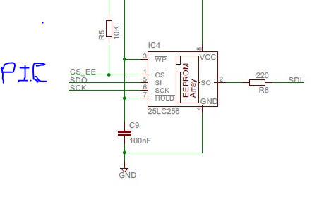
here is the 25LC512 chip's electrical circuit.
As it was described here in the forum, the connections are correct, I implemented the hardware, I believe it is an error in my code, because it is not even writing in the external memory, when I read, a symbol <0> |
|
|
Ttelmah
Joined: 11 Mar 2010
Posts: 20058
|
|
| Posted: Thu Mar 08, 2018 3:03 pm |
|
|
You don't show the PIC PINs used.
In your earlier post you say:
SDi -> RB0
RB0 is the SDI pin on the PIC. This needs to connect to the SO pin on the chip. Same comment applies to the SI pin on the memory that needs to go to RC7. |
|
|
|


