| View previous topic :: View next topic |
| Author |
Message |
irmanao
Joined: 08 Apr 2015
Posts: 77


|
| Problem with simple lcd test-SOLVED |
 Posted: Sat May 20, 2017 11:20 am Posted: Sat May 20, 2017 11:20 am |
 |
|
Hey guys, i'm trying to make this 16*2 LCD work with the 18f4550 but i can't make it work. I've re-checked the pin connections. A led flash test also works. Here's the code and the driver i used.(compiler:5.008)
code:
| Code: | #include <18F4550.h>
#fuses INTRC_IO, NOWDT, PUT ,BROWNOUT, NOLVP, CPUDIV1
#use delay(clock=8000000)
#include <flex_lcd.h>
void main()
{
delay_ms(500);
lcd_init();
while(1)
{
lcd_putc("\f not\n");
lcd_putc(" working");
delay_ms(500);
}
} |
driver | Code: | //---------------------------------------------------
#define LCD_DB4 PIN_D4
#define LCD_DB5 PIN_D5
#define LCD_DB6 PIN_D6
#define LCD_DB7 PIN_D7
#define LCD_E PIN_D3
#define LCD_RS PIN_D2
#define LCD_RW PIN_D1
#define lcd_type 2 // 0=5x7, 1=5x10, 2=2 lines
#define lcd_line_two 0x40 // LCD RAM address for the 2nd line
int8 const LCD_INIT_STRING[4] =
{
0x20 | (lcd_type << 2), // Func set: 4-bit, 2 lines, 5x8 dots
0xc, // Display on
1, // Clear display
6 // Increment cursor
};
//=================================================================
void lcd_send_nibble(int8 nibble);
void lcd_send_byte(int8 address, int8 n);
void lcd_init(void);
void lcd_gotoxy(int8 x, int8 y);
void lcd_putc(char c);
//=================================================================
//-------------------------------------------------------------
void lcd_send_nibble(int8 nibble)
{
// Note: !! converts an integer expression
// to a boolean (1 or 0).
output_bit(LCD_DB4, !!(nibble & 1));
output_bit(LCD_DB5, !!(nibble & 2));
output_bit(LCD_DB6, !!(nibble & 4));
output_bit(LCD_DB7, !!(nibble & 8));
delay_cycles(20);
output_high(LCD_E);
delay_us(50);
output_low(LCD_E);
}
//-----------------------------------
// This sub-routine is only called by lcd_read_byte().
// It's not a stand-alone routine. For example, the
// R/W signal is set high by lcd_read_byte() before
// this routine is called.
//----------------------------------------
// Send a byte to the LCD.
void lcd_send_byte(int8 address, int8 n)
{
output_low(LCD_RS);
if(address)
output_high(LCD_RS);
else
output_low(LCD_RS);
delay_cycles(10);
output_low(LCD_E);
lcd_send_nibble(n >> 4);
lcd_send_nibble(n & 0xf);
}
//----------------------------
void lcd_init(void)
{
int8 i;
output_low(LCD_RS);
output_low(LCD_E);
delay_ms(200);
for(i=0 ;i < 3; i++)
{
lcd_send_nibble(0x03);
delay_ms(10);
}
lcd_send_nibble(0x02);
for(i=0; i < sizeof(LCD_INIT_STRING); i++)
{
lcd_send_byte(0, LCD_INIT_STRING[i]);
// If the R/W signal is not used, then
// the busy bit can't be polled. One of
// the init commands takes longer than
// the hard-coded delay of 60 us, so in
// that case, lets just do a 5 ms delay
// after all four of them.
delay_ms(10);
}
}
//----------------------------
void lcd_gotoxy(int8 x, int8 y)
{
int8 address;
if(y != 1)
address = lcd_line_two;
else
address=0;
address += x-1;
lcd_send_byte(0, 0x80 | address);
}
//-----------------------------
void lcd_putc(char c)
{
switch(c)
{
case '\f':
lcd_send_byte(0,1);
delay_ms(4);
break;
case '\n':
lcd_gotoxy(1,2);
break;
case '\b':
lcd_send_byte(0,0x10);
break;
default:
lcd_send_byte(1,c);
break;
}
}
//------------------------------
|
thanks
Last edited by irmanao on Sun May 21, 2017 7:13 am; edited 3 times in total |
|
 |
Ttelmah
Joined: 11 Mar 2010
Posts: 20097
|
|
| Posted: Sat May 20, 2017 11:51 am |
|
|
I'd suggest one thing.
First make sure you turn off the peripherals on the port you are using.
The SPP, and the ECCP peripherals are both on the port D pins, and these have priority over the standard peripheral pins, and depending on the compiler version these may need to be explicitly turned off.
Next thing. Add a delay before trying to initialise the LCD.
LCD's take a long time to wake, compared to the PIC. You should wait for something like 0.5 seconds before trying to initialise the LCD.
Then delay after sending the text to the LCD. The poor thing may well not display correctly if it is being updated 'non stop'. |
|
|
irmanao
Joined: 08 Apr 2015
Posts: 77
|
|
| Posted: Sat May 20, 2017 12:24 pm |
|
|
I've added the delays but to no avail. I don't know how to disable those peripherals. Any tips as to where i should look it up? I've checked the datasheet but couldn't find anything on it.
thanks |
|
|
Ttelmah
Joined: 11 Mar 2010
Posts: 20097
|
|
| Posted: Sat May 20, 2017 12:41 pm |
|
|
| Code: |
setup_psp(PSP_DISABLED);
setup_ccp1(CCP_OFF);
|
What voltage have you got on the bias pin?. |
|
|
irmanao
Joined: 08 Apr 2015
Posts: 77
|
|
| Posted: Sun May 21, 2017 4:28 am |
|
|
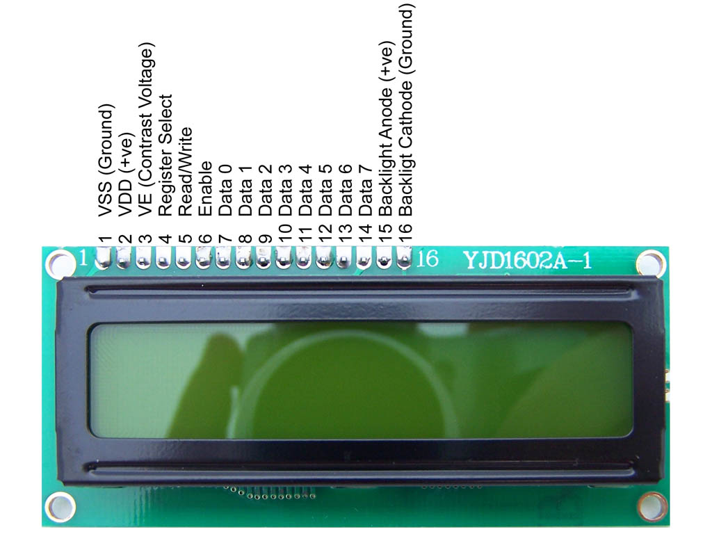
Which one is the bias pin?
 |
|
|
ezflyr
Joined: 25 Oct 2010
Posts: 1019
Location: Tewksbury, MA
|
|
| Posted: Sun May 21, 2017 4:49 am |
|
|
Hi,
Pin #3, also known as the contrast pin..
_________________
John
If it's worth doing, it's worth doing in real hardware! |
|
|
temtronic
Joined: 01 Jul 2010
Posts: 9641
Location: Greensville,Ontario
|
|
| Posted: Sun May 21, 2017 5:06 am |
|
|
Yes, #3 is correct. Check the LCD datasheet, typically they need about .5 volts, though I have a batch here that that don't need it connected at all and they work ! You can put a 10K pot to supply the voltage to the LCD VE pin. When 'happy' with the contrast, replace pot with 2 fixed resistors. I've got one with 100K to +5, 1K to GND though different makes need different voltage to VE.
If it still doesn't work, re-check your wiring...as I know the 4550 will control the LCD, the flex driver does work and most 1602 LCDs work fine.
Jay |
|
|
irmanao
Joined: 08 Apr 2015
Posts: 77
|
|
| Posted: Sun May 21, 2017 5:09 am |
|
|
I had a voltage divider there but changed it to a more fitting pot. Now all the LCD's characters are black even when the pic is erased. Any ideas?
thanks |
|
|
temtronic
Joined: 01 Jul 2010
Posts: 9641
Location: Greensville,Ontario
|
|
| Posted: Sun May 21, 2017 7:06 am |
|
|
well....
1) connect the LCD module , directly to the 4550 and use the originall flex driver. That combination does work, I know it did 3-4-5 years ago.....
Once you've confirmed it does THEN rewire/recode for the I2C version. It it fails then you KNOW it's 'something' in the I2C driver NOT the LCD module or the PIC.
as a general comment, you're not really saving any pins or time adding an I2C port to the PIC to control the LCD module so I assume this is more of a school project ?
Jay |
|
|
irmanao
Joined: 08 Apr 2015
Posts: 77
|
|
| Posted: Sun May 21, 2017 7:10 am |
|
|
I added to the code this: and it works as expected. I missed that somehow. Anyway thank you all for your kind help. By the way i didn't have to disable any peripherals in my case.
thanks |
|
|
Ttelmah
Joined: 11 Mar 2010
Posts: 20097
|
|
| Posted: Sun May 21, 2017 7:29 am |
|
|
| It should not need that, unless you have a #use fast_io somewhere in your code that you are not showing. |
|
|
PCM programmer
Joined: 06 Sep 2003
Posts: 21708
|
|
| Posted: Sun May 21, 2017 7:45 am |
|
|
That's what I think, too. Also he has removed this section from the
driver, as shown in his first post:
| Code: |
// If you only want a 6-pin interface to your LCD, then
// connect the R/W pin on the LCD to ground, and comment
// out the following line.
#define USE_LCD_RW 1
|
If that's not in there, it's the same thing as commenting it out, which
means he's using a 6-pin interface. But he never told us this.
He has removed all conditional blocks for that #define, so he has
actually made it into a 6-pin only driver.
So if he's got a secret #use fast_io, and he's using 6-pin mode, that
explains why setting Port D to all outputs would make it work. In 6-pin
mode you never have to read the busy bit, so all pins can be outputs all
the time.
He has also increased the size of delays throughout the driver, I guess in
an attempt to make it work. |
|
|
irmanao
Joined: 08 Apr 2015
Posts: 77
|
|
| Posted: Sun May 21, 2017 1:00 pm |
|
|
I am not using fast_io and i have connected all 7 pins including the r/w to the pic. I was just trying to make this lcd work with this driver i had.  |
|
|
PCM programmer
Joined: 06 Sep 2003
Posts: 21708
|
|
|
|


