| View previous topic :: View next topic |
| Author |
Message |
sysysy
Joined: 17 Nov 2010
Posts: 38
Location: 121


|
| DC motors speed synchronization issue |
 Posted: Thu Dec 02, 2010 9:14 pm Posted: Thu Dec 02, 2010 9:14 pm |
 |
|
Hi,
I am making a robot car with 2 wheels that control by 2 independent dc motor.(2 same model type DC motor)
In current stage, i'm having some difficulties.
i manage to control both of my dc motor moving forward, but the problem is how to synchronous their speed?
1 moving faster and another one slower.
Mean the both motor RPM is different?
Anyone can give me a solution, how to synchronous both motor speed?
Is it with using feedback encoder? if so, may i know the operating theory and how to build an encoder circuit?
Thx.
Regards,
sysysy. |
|
 |
temtronic
Joined: 01 Jul 2010
Posts: 9104
Location: Greensville,Ontario
|
|
| Posted: Sat Dec 04, 2010 7:39 am |
|
|
Yes, encoders are the way to go.
Simply...Each drive motor will need a disk attached to the shaft, with either slots cut out or a 'grating'(black stripes). The size and qty of slots is important.
You'll also need a slotted optocoupler style encoder.
Operation is simple.
As the wheel spins, the disc's black lines or slots create pulses that are fed to the PIC. The faster it rotates, the more pulses.
The PIC then has to read the signals to determine the speed and direction of that wheel. Naturally you need two complete setups. The PIC then has to compare the two readings and take the appropriate action, either by slowing down the faster wheel, or by speeding up the slower wheel (there are differences).
While it sounds complicated, take it in steps, and you'll get a working robot in a week or so.
Since we do not have info on any of the hardware, we can't help you anymore. However Google will show you thousands of examples of code.
Hint,,,computer mice operate this way..2 complete systems, if you can hack (build) then modify a mouse! Did that years ago...the data is now serial and can be read by the PIC via serial port. Again use Google to help you! |
|
|
sysysy
Joined: 17 Nov 2010
Posts: 38
Location: 121
|
|
| Posted: Sat Dec 04, 2010 8:04 am |
|
|
Thanks for the reply 
From the information that I searched is connected the optical disc(encoder) to the back shaft of my dc motor.
But my original motor is not like this, I wonder should I modify my motor by my own and feel like complicated.
Below is the difference between the encoder motor and the original motor that I have:
1. dc motor with the encoder

2. dc motor that I have
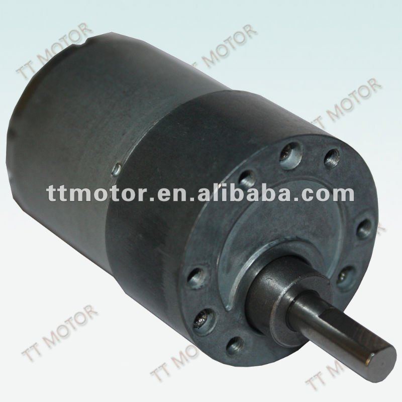
Is it possible I still can modify my own motor?
Thanks alot.
regards,
sysysy |
|
|
SherpaDoug
Joined: 07 Sep 2003
Posts: 1640
Location: Cape Cod Mass USA
|
|
| Posted: Sat Dec 04, 2010 8:47 am |
|
|
You can put the encoder disk anywhere in the drive train. It is generally preferred to put it on the motor before the reducing gears as this gives a higher speed and does not require the lines to be as fine as on a lower speed shaft. But you can put the disk on the wheel axle, or even paint the encoder stripes on the side of the rim of the wheel itself.
For my first robot (1980) I just painted a black spot on the shiny motor shafts so my 8085 could count the shaft revolutions with photocells. It was crude, but it allowed me to drive a straight line.
_________________
The search for better is endless. Instead simply find very good and get the job done. |
|
|
sysysy
Joined: 17 Nov 2010
Posts: 38
Location: 121
|
|
| Posted: Sat Dec 04, 2010 1:46 pm |
|
|
Hi SherpaDoug,
Thanks for the suggestion.
Anyway, I not really understand how can make it?
From what temtronic say,
| Quote: |
As the wheel spins, the disc's black lines or slots create pulses that are fed to the PIC. The faster it rotates, the more pulses.
|
Why the black lines will create pulses?
OK, when the shaft rotate, the disc will rotate as well?
But what is the things that help us to scan and count black lines?
How it tell the micro-controller?
Thanks.
regards,
sysysy |
|
|
SherpaDoug
Joined: 07 Sep 2003
Posts: 1640
Location: Cape Cod Mass USA
|
|
| Posted: Sat Dec 04, 2010 2:35 pm |
|
|
I used an older version of this chip:
http://search.digikey.com/scripts/DkSearch/dksus.dll?Detail&name=516-2182-ND
The data sheet describes how to create the striped target and how it works. Basically when the photocell sees black it outputs one logic state, when it sees white (or shiny metal) it outputs the other logic state. The two signals from sensors on two motors go into two counters that are read by software. If one counter is counting faster then the other then its motor must be spinning faster.
_________________
The search for better is endless. Instead simply find very good and get the job done. |
|
|
|


