 |
 |
| View previous topic :: View next topic |
| Author |
Message |
Warday
Joined: 21 May 2021
Posts: 11


|
| RS485 Modbus |
 Posted: Mon Aug 23, 2021 1:59 pm Posted: Mon Aug 23, 2021 1:59 pm |
 |
|
Hi, I’m trying a simple Modbus communication using RS485. I have already used RS485 to communicate thru serial without problem. Now I want to implement Modbus protocol. I only required to read and edit 2 registers (one is position and the other is inclination).
I have modified ex_modbus_slave.c to do so. To read and modify register I’m using python and raspberry. Unfortunately it always say that there is no communication (Timeout error). I try to use Modbus Poll, and Modbus scan to read the registers but the communications always fail (Same error). What can I be doing wrong? I use 0x0A which is address 10.
pic code (CCS)
I only modify:
uncomment #define USE_WITH_PC 1
change pic to 30f4012.h
change rx tx pin
define enable pin for rs485
#define MODBUS_ADDRESS 0x0A
Thats all.
| Code: |
#define USE_WITH_PC 1
#if defined(__PCD__)
#include <30f4012.h>
#fuses PR,HS,NOWDT
#use delay(clock=20M)
#elif defined(__PCH__)
#include <30f4012.h>
#fuses HS, NOWDT
#use delay(clock=20M)
#else
#include <30f4012.h>
#fuses HS,NOWDT
#use delay(clock=20M)
#endif
#define MODBUS_TYPE MODBUS_TYPE_SLAVE
#define MODBUS_SERIAL_TYPE MODBUS_RTU //use MODBUS_ASCII for ASCII mode
#define MODBUS_SERIAL_RX_BUFFER_SIZE 64
#define MODBUS_SERIAL_BAUD 9600
#ifndef USE_WITH_PC
#define MODBUS_SERIAL_INT_SOURCE MODBUS_INT_EXT
#if defined(__PCD__)
#define MODBUS_SERIAL_TX_PIN PIN_F3 // Data transmit pin
#define MODBUS_SERIAL_RX_PIN PIN_F2 // Data receive pin
//The following should be defined for RS485 communication
#define MODBUS_SERIAL_ENABLE_PIN PIN_R4 // Controls DE pin for RS485
#define MODBUS_SERIAL_RX_ENABLE PIN_R3 // Controls RE pin for RS485
#else
#define MODBUS_SERIAL_TX_PIN PIN_F3 // Data transmit pin
#define MODBUS_SERIAL_RX_PIN PIN_F2 // Data receive pin
//The following should be defined for RS485 communication
#define MODBUS_SERIAL_ENABLE_PIN PIN_R4 // Controls DE pin for RS485
#define MODBUS_SERIAL_RX_ENABLE PIN_R3 // Controls RE pin for RS485
#endif
#else
#define MODBUS_SERIAL_INT_SOURCE MODBUS_INT_RDA
#endif
#include <modbus.c>
#define MODBUS_ADDRESS 0x0A
int8 swap_bits(int8 c)
{
return ((c&1)?128:0)|((c&2)?64:0)|((c&4)?32:0)|((c&8)?16:0)|((c&16)?8:0)
|((c&32)?4:0)|((c&64)?2:0)|((c&128)?1:0);
}
void main()
{
int8 coils = 0b00000101;
int8 inputs = 0b00001001;
int16 hold_regs[] = {0x8800,0x7700,0x6600,0x5500,0x4400,0x3300,0x2200,0x1100};
int16 input_regs[] = {0x1100,0x2200,0x3300,0x4400,0x5500,0x6600,0x7700,0x8800};
int16 event_count = 0;
setup_adc_ports(NO_ANALOGS);
modbus_init();
Rule 10 same as ex_modbus_slave.c
|
Pycode
| Code: |
import minimalmodbus
instrument = minimalmodbus.Instrument('/dev/ttyUSB0', 10)
instrument.serial.port
instrument.serial.baudrate = 9600
instrument.serial.bytesize = 8
instrument.serial.timeout = 0.2
instrument.mode = minimalmodbus.MODE_RTU # rtu or ascii mode
instrument.clear_buffers_before_each_transaction = True
print(instrument)
register= instrument.read_register(0x01)
print(register)
|
Thanks for the help. |
|
 |
Jerson
Joined: 31 Jul 2009
Posts: 122
Location: Bombay, India

|
|
| Posted: Mon Aug 23, 2021 8:04 pm |
|
|
| Since you have already got a working modbus implementation on RS485, I would guess your problem is on the host Rasp Pi side. Try increasing the polling timeout and/or the time between polls to see which one it is that fixes the problem. |
|
|
Ttelmah
Joined: 11 Mar 2010
Posts: 19215
|
|
| Posted: Tue Aug 24, 2021 1:09 am |
|
|
You are selecting USE_WITH_PC. This is designed for when the PIC
system is being attached via RS232 to a PC, and it then has to handle the
RS485, using INT_EXT, not the UART. Is this what you are doing?. .
It requires hardware changes to the Modbus wiring (with the RX line
connected to the INT_EXT line).
I think you are simply setting the slave up wrong..... |
|
|
temtronic
Joined: 01 Jul 2010
Posts: 9093
Location: Greensville,Ontario
|
|
| Posted: Tue Aug 24, 2021 6:05 am |
|
|
hmm... curious about this...
| Quote: | | '/dev/ttyUSB0', 10) |
in your Python code,
I assume means the Pie is looking for a USB device on the serial port ? Or do you have a USB<.RS485 adapter on the USB port ? Or do you need to say ... '/dev/ttyRS485', 10) ?? or something else ??
You may need to explain what hardware actually connects electrons from PIC to PIE. |
|
|
Jerson
Joined: 31 Jul 2009
Posts: 122
Location: Bombay, India
|
|
| Posted: Tue Aug 24, 2021 6:26 am |
|
|
| On linux systems like the RaspPi /dev/ttyUSB0 usually signifies a USB serial port. The 10 possibly is a timeout value(I suspect) |
|
|
Warday
Joined: 21 May 2021
Posts: 11
|
|
| Posted: Tue Aug 24, 2021 7:25 am |
|
|
I have a RS482 to usb adapter and a HW-97 RS482 for the pic. Whit that I can convert normal serial communication to rs485. That works ok. Now I want to implement Modbus on that communication.
| Jerson wrote: | | Since you have already got a working modbus implementation on RS485, I would guess your problem is on the host Rasp Pi side. Try increasing the polling timeout and/or the time between polls to see which one it is that fixes the problem. |
I have make RS485 work as a normal serial communication not Modbus.
| Ttelmah wrote: | You are selecting USE_WITH_PC. This is designed for when the PIC
system is being attached via RS232 to a PC, and it then has to handle the
RS485, using INT_EXT, not the UART. Is this what you are doing?. .
It requires hardware changes to the Modbus wiring (with the RX line
connected to the INT_EXT line).
I think you are simply setting the slave up wrong..... |
That can be the problem. I will check it out.
| temtronic wrote: | hmm... curious about this...
'/dev/ttyUSB0', 10)
in your Python code,
I assume means the Pie is looking for a USB device on the serial port ? Or do you have a USB<.RS485 adapter on the USB port ? Or do you need to say ... '/dev/ttyRS485', 10) ?? or something else ??
you may need to explain what hardware actually connects electrons from PIC to PIE. |
'/dev/ttyUSB0' is the rs482 to serial converter and the 10 is the device id. The python code works in decimal.
Thanks for the answers |
|
|
temtronic
Joined: 01 Jul 2010
Posts: 9093
Location: Greensville,Ontario
|
|
| Posted: Tue Aug 24, 2021 7:40 am |
|
|
re: ... | Quote: | I have a RS482 to usb adapter and a HW-97 RS482 for the pic
|
I have to ask HOW do the adapters control the direction of RS-485 data ?
BTW I didn't find HW-97 to be an adapter...seems to be a gun and a highway.....sigh...good ol Google !
Maybe post a link to the adapters ? |
|
|
Warday
Joined: 21 May 2021
Posts: 11
|
|
| Posted: Tue Aug 24, 2021 8:15 am |
|
|
| temtronic wrote: | re: ...I have a RS482 to usb adapter and a HW-97 RS482 for the pic
I have to ask HOW do the adapters control the direction of RS-485 data ?
BTW I didn't find HW-97 to be an adapter...seems to be a gun and a highway.....sigh...good ol Google !
Maybe post a link to the adapters ? |
pic adapter
https://protosupplies.com/product/max485-ttl-to-rs-485-interface-module/
USB adapter
https://www.twinschip.com/USB_to_RS485_Converter_Adapter
As difference as serial, RS485 is half-duplex communication device. You can use is it with standard communication (printf("PWM= %d\r\n",PWM); to do so you only have to properly select DE RE state to indicate if you are transmitting or receiving. That’s works without problem. Now I want to implement Modbus protocol. Modbus library have already the RE DE configuration for RS485. |
|
|
Warday
Joined: 21 May 2021
Posts: 11
|
|
| Posted: Tue Aug 24, 2021 9:00 am |
|
|
| Ttelmah wrote: | You are selecting USE_WITH_PC. This is designed for when the PIC
system is being attached via RS232 to a PC, and it then has to handle the
RS485, using INT_EXT, not the UART. Is this what you are doing?. .
It requires hardware changes to the Modbus wiring (with the RX line
connected to the INT_EXT line).
I think you are simply setting the slave up wrong..... |
I made the next test. I change
#define MODBUS_SERIAL_INT_SOURCE MODBUS_INT_EXT
to MODBUS_INT_RDA to use UART. It fails.
I change conection and use INT0 (30f4012) with INT_EXT it fails. |
|
|
Jerson
Joined: 31 Jul 2009
Posts: 122
Location: Bombay, India
|
|
| Posted: Tue Aug 24, 2021 9:29 am |
|
|
Seeing the adapters you are using, I assume the PIC side would be handled well by the library which will switch TX/RX direction as needed by the code.
On the Python side, you would always be in receive mode when using the USB-485 converter unless you try sending some data Py->PIC. That is when the USB converter will switch direction from Py->PIC, send the data, and then after a fixed internal delay fall back to receive mode again PIC->Py. This timeout along with the latency of your PIC would normally become the bottleneck for modbus. So, start high with timeout of 1000ms and work your way down.
The way I would check this is to use a serial monitor on the RaspPi, and let the PIC keep sending some known data patterns. Once you receive the data patterns clearly, you can then check the reverse direction. |
|
|
Warday
Joined: 21 May 2021
Posts: 11
|
|
| Posted: Tue Aug 24, 2021 12:53 pm |
|
|
| Jerson wrote: | Seeing the adapters you are using, I assume the PIC side would be handled well by the library which will switch TX/RX direction as needed by the code.
On the Python side, you would always be in receive mode when using the USB-485 converter unless you try sending some data Py->PIC. That is when the USB converter will switch direction from Py->PIC, send the data, and then after a fixed internal delay fall back to receive mode again PIC->Py. This timeout along with the latency of your PIC would normally become the bottleneck for modbus. So, start high with timeout of 1000ms and work your way down.
The way I would check this is to use a serial monitor on the RaspPi, and let the PIC keep sending some known data patterns. Once you receive the data patterns clearly, you can then check the reverse direction. |
Well i try ex_modbus_master.c and set it to work with pc. It seems to worked ok. I have problem with slave only.
Edit: Seems that the problem is on RX. The devise sends information but cand receive. (I make the master change register 3 to 0x1111 if it could read the coils and 0x2222 if it couldn’t. it set always 0x2222)
 |
|
|
Ttelmah
Joined: 11 Mar 2010
Posts: 19215
|
|
| Posted: Wed Aug 25, 2021 7:35 am |
|
|
As I have already pointed oot in another thread, 'USE_WITH_PC' means
the modbus will be setup to use INT_EXT to trigger the receive, not INT_RX. |
|
|
Warday
Joined: 21 May 2021
Posts: 11
|
|
| Posted: Thu Aug 26, 2021 2:57 pm |
|
|
| Ttelmah wrote: | As I have already pointed oot in another thread, 'USE_WITH_PC' means
the modbus will be setup to use INT_EXT to trigger the receive, not INT_RX. |
I already try that. I used INT_EXT and INT_RDA
Fixed. The problem whas that the default grup was EVEN and software default was NONE.
Sujesstions to do it yourself.
1º when trying the demo clean it and use your configuration
Example:
| Code: |
#include <30f4012.h>
#fuses HS,NOWDT
#use delay(clock=20M)
#define MODBUS_PROTOCOL MODBUS_PROTOCOL_SERIAL
#define MODBUS_TYPE MODBUS_TYPE_SLAVE
#define MODBUS_SERIAL_TYPE MODBUS_RTU //use MODBUS_ASCII for ASCII mode
#define MODBUS_SERIAL_RX_BUFFER_SIZE 64
#define MODBUS_SERIAL_BAUD 9600
#define MODBUS_SERIAL_INT_SOURCE MODBUS_INT_RDA
#define MODBUS_SERIAL_TX_PIN PIN_F3 // Data transmit pin
#define MODBUS_SERIAL_RX_PIN PIN_F2 // Data receive pin
//The following should be defined for RS485 communication
#define MODBUS_SERIAL_ENABLE_PIN PIN_E4 // Controls DE pin for RS485
#define MODBUS_SERIAL_RX_ENABLE PIN_E3 // Controls RE pin for RS485
#include <modbus.c>
#define MODBUS_ADDRESS 0xF7
|
In my case I use Timer 1 to control one pid so in the future I will have to change modbus.c default timer. I use UART so i use:
#define MODBUS_SERIAL_INT_SOURCE MODBUS_INT_RDA
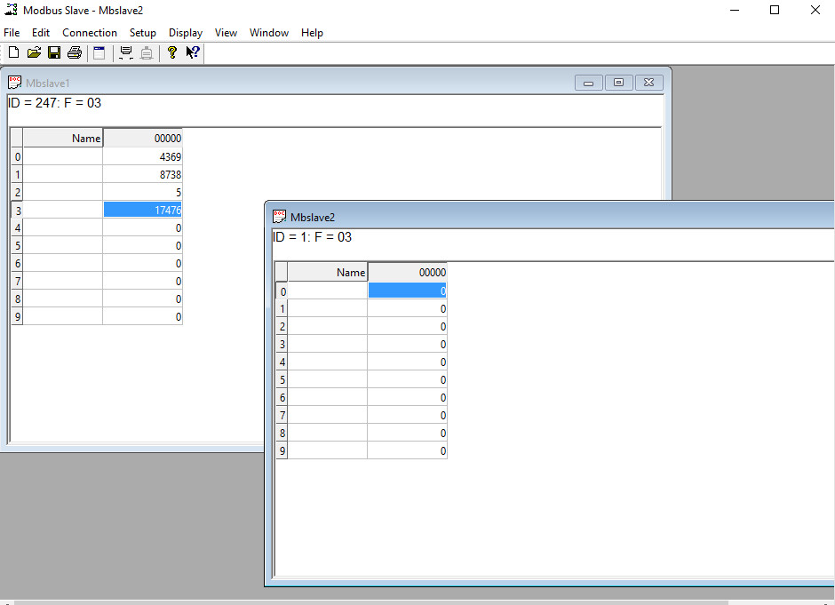
Example code in python(Raspbian): I use inst to speak devise 247 (0xF7) and inst2 (0) to speak to all (you can only write register). All work perfect. Hope it helps others with the same problem. Thanks for all!
| Code: |
import minimalmodbus
inst = minimalmodbus.Instrument('/dev/ttyUSB0', 247 )
inst.serial.stopbits = 1
inst.serial.baudrate = 9600
inst.serial.bytesize = 8
inst.serial.timeout = 0.2
inst.serial.parity = minimalmodbus.serial.PARITY_EVEN
inst.clear_buffers_before_each_transaction = True
inst2 = minimalmodbus.Instrument('/dev/ttyUSB0', 0, debug=True )
inst2.serial.stopbits = 1
inst2.serial.baudrate = 9600
inst2.serial.bytesize = 8
inst2.serial.timeout = 0.2
inst2.serial.parity = minimalmodbus.serial.PARITY_EVEN
inst2.clear_buffers_before_each_transaction = True
# Registernumber, number of decimals
inst2.write_register(0x00, 1100, 0,6)
print("Old")
print(inst.read_register(0x00))
print(inst.read_register(0x01))
print(inst.read_register(0x02))
print(inst.read_register(0x03))
print(inst.read_register(0x04))
print(inst.read_register(0x05))
print(inst.read_register(0x06))
print(inst.read_register(0x07))
print("New")
inst.write_register(0x00, 1, 0,6)
inst.write_register(0x01, 2, 0,6)
inst.write_register(0x02, 3, 0,6)
inst.write_register(0x03, 4, 0,6)
inst.write_register(0x04, 5, 0,6)
inst.write_register(0x05, 6, 0,6)
inst.write_register(0x06, 7, 0,6)
inst.write_register(0x07, 8, 0,6)
print(inst.read_register(0x00))
print(inst.read_register(0x01))
print(inst.read_register(0x02))
print(inst.read_register(0x03))
print(inst.read_register(0x04))
print(inst.read_register(0x05))
print(inst.read_register(0x06))
print(inst.read_register(0x07))
|
Last edited by Warday on Fri Aug 27, 2021 9:38 am; edited 2 times in total |
|
|
Ttelmah
Joined: 11 Mar 2010
Posts: 19215
|
|
| Posted: Fri Aug 27, 2021 12:50 am |
|
|
You are missing the point.
The RX signal has to go _both_ to INT_EXT, and the receive pin.
The INT_EXT is used to 'trigger' the start of the receive, but the data
still has to actually be received. |
|
|
Warday
Joined: 21 May 2021
Posts: 11
|
|
| Posted: Fri Aug 27, 2021 9:31 am |
|
|
| Ttelmah wrote: | You are missing the point.
The RX signal has to go _both_ to INT_EXT, and the receive pin.
The INT_EXT is used to 'trigger' the start of the receive, but the data
still has to actually be received. |
Hi. It’s depends in how you configure the device.
If you read the source code of the library you will find an interrupt selector that switch between INT_RDA, INT_RDA1, INT_RDA2, INT_RDA3, INT_INI or INT_INI0. If you set MODBUS_INT_EXT (Default) It will select INT_INI_, INT_INI0 depending in your devise. I change the default configuration to INT_RDA because I wanted to use UART. The communication works perfect with INT_RDA, RS485 and modbus protocol, and INT_INI0 is free to use (I use it to detect a dead end). As I sed, my problem was the default configuration.
Note that in previous post I sed that I could fix the problem and what was it.
Greetings !!! |
|
|
|
|
You cannot post new topics in this forum
You cannot reply to topics in this forum
You cannot edit your posts in this forum
You cannot delete your posts in this forum
You cannot vote in polls in this forum
|
Powered by phpBB © 2001, 2005 phpBB Group
|

