 |
 |
| View previous topic :: View next topic |
| Author |
Message |
viki2000
Joined: 08 May 2013
Posts: 233


|
| PIC24HJ64GP202 and UART |
 Posted: Tue May 09, 2017 2:01 am Posted: Tue May 09, 2017 2:01 am |
 |
|
I used a simple test program to blink a LED and works, and then I wanted to send serial RS232 to PC using UART. I have a USB to RS232 TTL converter that works and I can see also the RS232 signals on oscilloscope.
On PC I use RealTerm serial terminal software.
I used next test code for UART RS232:
| Code: | #include <24HJ64GP202.h>
#FUSES NOWDT //No Watch Dog Timer
#FUSES NOWRTB //Boot block not write protected
#FUSES NOBSS //No boot segment
#FUSES NORBS //No Boot RAM defined
#FUSES NOWRTSS //Secure segment not write protected
#FUSES NOSSS //No secure segment
#FUSES NORSS //No secure segment RAM
#FUSES NOWRT //Program memory not write protected
#FUSES NOPROTECT //Code not protected from reading
#FUSES IESO //Internal External Switch Over mode enabled
#FUSES NOOSCIO //OSC2 is clock output
#FUSES IOL1WAY //Allows only one reconfiguration of peripheral pins
#FUSES CKSFSM //Clock Switching is enabled, fail Safe clock monitor is enabled
#FUSES WINDIS //Watch Dog Timer in non-Window mode
#FUSES PUT128 //Power On Reset Timer value 128ms
#FUSES NOALTI2C1 //I2C1 mapped to SDA1/SCL1 pins
#FUSES NOJTAG //JTAG disabled
#use delay(internal=80000000)
#pin_select U1TX=PIN_B7
#pin_select U1RX=PIN_B8
#use rs232(UART1, BAUD=9600)
void main()
{
int8 x=0;
while(TRUE)
{
putc(x);
x++;
}
} |
The problem is that I see only “0” on PC serial terminal software.
Do you have any suggestions to debug it? |
|
 |
Ttelmah
Joined: 11 Mar 2010
Posts: 19221
|
|
| Posted: Tue May 09, 2017 2:11 am |
|
|
Remember that binary '0', is not the ASCII character "0".
80% of what you send with the counter, will be undisplayable characters (including things like backspace etc.)....
| Code: |
void main()
{
int8 x=0;
while(TRUE)
{
printf("%d\n", x);
x++;
}
}
|
Which will then print the numbers in human readable form, with a line feed between each one.
Your fourth and fifth characters sending the numbers directly, will be ETX and EOT, which the terminal program may well stop receiving, when they arrive.... |
|
|
viki2000
Joined: 08 May 2013
Posts: 233
|
|
| Posted: Tue May 09, 2017 2:44 am |
|
|
Thank you for reply.
RealTerm serial terminal lets you configure what you see as int8 or int16 or ASCII or HEX a lot of other possibilities. There is no problem here.
I do not know what the problem was, but now it works with my code above. Maybe it was just a wiring, a contact, noise.
I try now to send 16bit data on serial terminal and I cannot see it proper on serial terminal.
I use in main next code:
| Code: | void main()
{
signed int16 x=0;
while(TRUE)
{
putc(x && 0xFF);
putc(x >> 8);
x++;
}
} |
What do I miss here? |
|
|
Ttelmah
Joined: 11 Mar 2010
Posts: 19221
|
|
| Posted: Tue May 09, 2017 4:35 am |
|
|
&& is 'logical and', not 'bitwise and'. Also shifting a signed value, may not give what you expect. Use make8. More efficient anyway.
| Code: |
putc(make8(x,0)); //LSB
putc(make8(x,1)); //MSB
|
|
|
|
viki2000
Joined: 08 May 2013
Posts: 233
|
|
| Posted: Tue May 09, 2017 4:49 am |
|
|
Unbelievable childish mistake, because I have copied more code from an XC16 online example:
it should be
Now works fine. |
|
|
viki2000
Joined: 08 May 2013
Posts: 233
|
|
| Posted: Thu Jun 01, 2017 6:40 am |
|
|
I have a glitch.
I send 2 bytes on UART RS-232 using next code:
| Code: | #include <24HJ64GP202.h>
#use delay(internal=80MHz)
#FUSES FRC_PLL
#FUSES NOWDT //No Watch Dog Timer
#FUSES NOWRTB //Boot block not write protected
#FUSES NOBSS //No boot segment
#FUSES NORBS //No Boot RAM defined
#FUSES NOWRTSS //Secure segment not write protected
#FUSES NOSSS //No secure segment
#FUSES NORSS //No secure segment RAM
#FUSES NOWRT //Program memory not write protected
#FUSES NOPROTECT //Code not protected from reading
#FUSES IESO //Internal External Switch Over mode enabled
#FUSES NOOSCIO //OSC2 is clock output
#FUSES IOL1WAY //Allows only one reconfiguration of peripheral pins
#FUSES CKSFSM //Clock Switching is enabled, fail Safe clock monitor is enabled
#FUSES WINDIS //Watch Dog Timer in non-Window mode
#FUSES PUT128 //Power On Reset Timer value 128ms
#FUSES NOALTI2C1 //I2C1 mapped to SDA1/SCL1 pins
#FUSES NOJTAG //JTAG disabled
#pin_select U1TX=PIN_B6
#pin_select U1RX=PIN_B7
#use rs232(UART1, BAUD=9600, ERRORS)
void main(){
int16 y;
while(TRUE)
{
for(y=0; y<32767; y=y+1){
//delay_ms(10);)
putc(make8(y,0)); //LSB
putc(make8(y,1)); //MSB
}
}
} |
At PC side I use a USB to RS232-TTL adapter and RealTerm software serial terminal.
Overall the communication works fine, but once in a while, seems regularly and depending by baud rate, I have a glitch, the numbers change (drop down) with a certain unexpected value.
You may see it here as graphic:
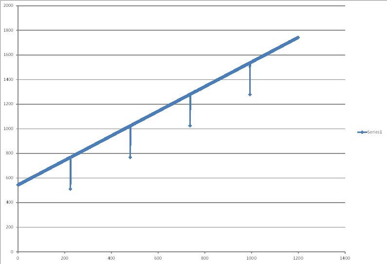
or in the next Excel file containing data captured from serial port using RealTerm.
https://goo.gl/WN82fn
How can I find from where is coming that error?
I noticed that in the above case of linear changing, it happens each 256 numbers in Excel table, but if I generate for example a sine wave, then that 256 may be a different number, but still repeated as regular glitch. |
|
|
viki2000
Joined: 08 May 2013
Posts: 233
|
|
| Posted: Thu Jun 01, 2017 7:35 am |
|
|
The number 256 above it seems it is just a coincidence.
I have also different other numbers as 82 or 85 or 115, random, but in the same time is the same number for one transmission, for one capture time.
It has nothing to do with CCS compiler. I tried also XC16, similar code, at 115000 baud rate, to generate a sine wave. It works, but the glitches are there.
For example here is the generated sine wave as chart in excel with the numbers received at serial port:
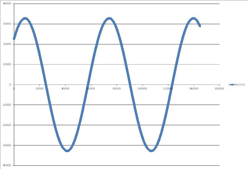
But when we “zoom in” by scaling the excel chart, then we see the glitches:
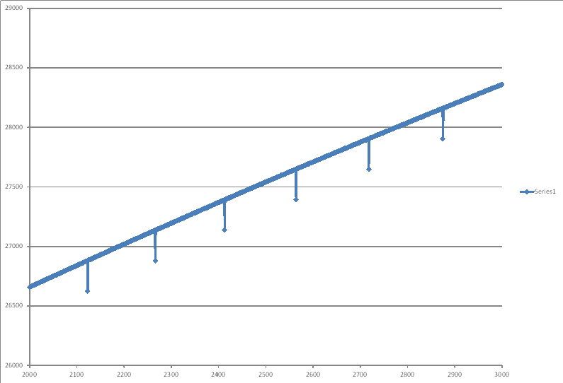
Here is the Excel file with the number and the chart:
https://goo.gl/zFCwUs
It seems is related with the serial port, maybe the USB-RS232 TTL adapter, a RS232 buffer or something similar?
Do you have any ideas how to trace the problem? |
|
|
Ttelmah
Joined: 11 Mar 2010
Posts: 19221
|
|
| Posted: Thu Jun 01, 2017 7:53 am |
|
|
How are you reconstructing the 16 bits at the receiving end?.
It has all the symptoms of something like a problem when the receive array/counter wraps at the end.
On 'tracing the data', remove your receiving program, and record perhaps 1KB of data from the serial port. Then read this and see if the glitch is there. |
|
|
viki2000
Joined: 08 May 2013
Posts: 233
|
|
| Posted: Thu Jun 01, 2017 8:44 am |
|
|
I have done further tests.
I have changed the USB-RS232 TTL adapter with another one. I have the same glitch.
Then I have used PIC16F1825 on 8bit instead f PIC24H on 16bit. I have the same problem.
If it is linear change indexed with 1 at the time, then the glitch appears at each 256 numbers.
This is the code used with PIC16F1825:
| Code: | #include <16F1825.h>
#fuses NOFCMEN ,NOIESO, NOCLKOUT, BROWNOUT, NOCPD, NOPROTECT, NOMCLR, NOPUT, NOWDT, INTRC_IO
#device ADC=10
#use delay(internal=32MHz)
#use rs232(baud=115200,parity=N,xmit=PIN_C4,rcv=PIN_C5,bits=8,stream=PORT1)
void main(){
int16 y;
while(TRUE)
{
for(y=0; y<32767; y=y+1){
//delay_ms(10);)
putc(make8(y,0)); //LSB
putc(make8(y,1)); //MSB
}
}
} |
What do I miss here? Why do I see that glitch?
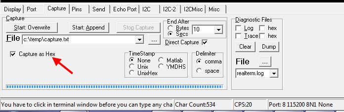
I use RealTerm serial terminal to capture data direct in a file as HEX.
Then I take that .txt file with HEX numbers inside and I import it into Excel and convert it to DEC to make the chart.
I have to look at the conversion formulas used in Excel, but is basically like this:
- Column A contains the HEX value captured directly from serial port
- Column B contains next formula =MOD(HEX2DEC(A2)+2^15;2^16)-2^15 to convert into DEC. |
|
|
Ttelmah
Joined: 11 Mar 2010
Posts: 19221
|
|
| Posted: Thu Jun 01, 2017 1:47 pm |
|
|
Why the maths?.
Max value is 32766. 32766+32768 = 65534, 65535 MOD 65536 is 65534. You then subtract 32768 to get back the number you first started with....
Same applied to all smaller numbers.
Seems a waste.
However the point I was making is to look at the hex data at the point when the glitch happens. My suspicion is perhaps something silly is happening possibly when the LSB is 0. Perhaps the alignment changes which confuses the Excel conversion. You need to narrow things down, and looking directly at the data can rule out Excel. |
|
|
viki2000
Joined: 08 May 2013
Posts: 233
|
|
| Posted: Thu Jun 01, 2017 1:50 pm |
|
|
I checked the raw hex data captured directly from serial port in a .txt file.
I see the glitch in that raw data.
For example:
02FE
02FF
0200
0301
0302
The problem is with 0200, it should be 0300.
03FE
03FF
0300
0401
0402
0403
The problem is with 0300, it should be 0400.
10FE
10FF
1000
1101
1102
1103
The problem is with 1000, it should be 1100.
61FE
61FF
6100
6201
6202
6203
The problem is with 6100, it should be 6200.
57FE
57FF
5700
5801
5802
5803
The problem is with 5700, it should be 5800.
6DFE
6DFF
6D00
6E01
6E02
6E03
The problem is with 6D00, it should be 6E00.
These values are from various moments, different baud rates, and different capture files.
I noticed a pattern, that glitch happens always when there is a change at a round number, but not on all round numbers.
Actually is the MSB byte when there is a change of the last (right) digit.
Any further suggestions?
Regarding the math, I got HEX values in Excel and I wanted to convert them to DEC. There is a formula in Excel HEX2DEC but not for 16bit signed, because I use also for sine wave with negative values, so I was inspired by next suggestion:
http://www.cypress.com/blog/daves-corner-dave-van-ess-blog/really-cool-hex-signed-interger-trick-excel |
|
|
Ttelmah
Joined: 11 Mar 2010
Posts: 19221
|
|
| Posted: Thu Jun 01, 2017 2:37 pm |
|
|
It looks like a reception order problem. MSB-LSB, rather than LSB,MSB.
So you are missing possibly the first byte (this is the classic problem of not having some form of sync marker - why data with reserved values is always preferred). Then hex2dec expects the MSB first, so takes the second byte as the MSB, and then uses the LSB from this word. At the 256byte 'jump', you then get the wrong MSB..... |
|
|
viki2000
Joined: 08 May 2013
Posts: 233
|
|
| Posted: Fri Jun 02, 2017 1:44 am |
|
|
The problem is found and solved.
Here it is what I have done.
Thinking that may be something particular with the numbers above, I decided to send all these numbers through UART by putting them in a small table.
I tested the next code:
| Code: | #include <16F1825.h>
#fuses NOFCMEN ,NOIESO, NOCLKOUT, BROWNOUT, NOCPD, NOPROTECT, NOMCLR, NOPUT, NOWDT, INTRC_IO
#device ADC=10
#use delay(internal=32MHz)
#use rs232(baud=115200,parity=N,xmit=PIN_C4,rcv=PIN_C5,bits=8,stream=PORT1)
CONST unsigned long Table[6] = {0x0100, 0x0200, 0x0300, 0x6D00, 0x6E00, 0x6F00};
void main(){
int8 i=0;
while(TRUE)
{
for(i=0; i<6; i=i+1){
delay_ms(100);
putc(make8(Table[i],1)); //MSB
putc(make8(Table[i],0)); //LSB
}
}
} |
I put the delay to observe them on the PC screen easy, but then I have tested also without delay by capturing them directly in a .txt file.
The problem is when I set RealTerm to show the numbers in HEX. They were shown with MSB and LSB interchanged. Then I realized the problem.
It was enough to change the order in the code: to send LSB first and MSB after that and the problem disappeared.
Why the problem appeared and I did not notice it?
Because I never watch the numbers of a sine wave and neither long number as 32000 in HEX, it is difficult. I watch them always in signed int16 and there you cannot see the problem.
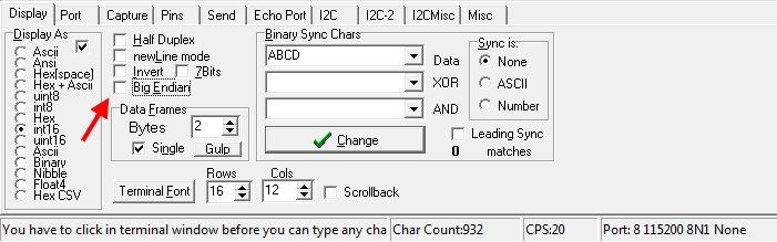
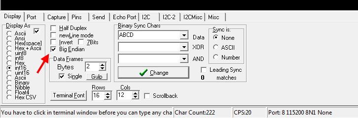
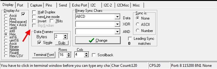
The problem comes from RealTerm settings, a small setting hard to be noticed at the first view.
When RealTerm is set to show the numbers in signed int16, then it lets you to change also Big endian, which means the way how RealTerm interpret which byte comes first: MSB or LSB.
When you set it to show the values in HEX then Big endian setting becomes grey, meaning disabled and the bytes are always interpreted as MSB first and LSB second.
When I captured the data, I always set RealTerm to show int16, but to capture it was set HEX, because it is easier to convert in DEC in Excel. The raw data looks as garbage ASCII and must go in other programs as for example Audacity I have used, which can resample and export as time domain, but then is not as “raw” as initial HEX, so I wanted to avoid that Audacity step and work directly with HEX.
I did not expect that RealTerm will ignore the Big endian setting when I capture directly in HEX.
It seems the setting with Big endian (enable/disable) applies only for what we see on the screen, but when we capture data and we set to be captured as HEX, then RealTerm always takes MSB first and LSB second.
It was confusion between RealTerm setting for displayed data, what I can see on screen and captured data as HEX.
Here are some screenshots with RealTerm settings:
Next code generates sine wave captured without glitches using RealTerm set to capture as HEX:
| Code: | #include <24HJ64GP202.h>
#include <math.h>
#use delay(internal=80MHz)
#FUSES NOWDT //No Watch Dog Timer
#FUSES NOWRTB //Boot block not write protected
#FUSES NOBSS //No boot segment
#FUSES NORBS //No Boot RAM defined
#FUSES NOWRTSS //Secure segment not write protected
#FUSES NOSSS //No secure segment
#FUSES NORSS //No secure segment RAM
#FUSES NOWRT //Program memory not write protected
#FUSES NOPROTECT //Code not protected from reading
#FUSES IESO //Internal External Switch Over mode enabled
#FUSES NOOSCIO //OSC2 is clock output
#FUSES IOL1WAY //Allows only one reconfiguration of peripheral pins
#FUSES CKSFSM //Clock Switching is enabled, fail Safe clock monitor is enabled
#FUSES WINDIS //Watch Dog Timer in non-Window mode
#FUSES PUT128 //Power On Reset Timer value 128ms
#FUSES NOALTI2C1 //I2C1 mapped to SDA1/SCL1 pins
#FUSES NOJTAG //JTAG disabled
#pin_select U1TX=PIN_B6
#pin_select U1RX=PIN_B7
#use rs232(UART1, BAUD=115200, ERRORS)
void main()
{
float x;
signed int16 y;
while(TRUE)
{
for(x=0; x<2*PI; x+=PI/32768){
y = 32767*sin(x);
putc(make8(y,1)); //MSB
putc(make8(y,0)); //LSB
}
}
} |
Last edited by viki2000 on Fri Jun 02, 2017 1:49 am; edited 1 time in total |
|
|
Ttelmah
Joined: 11 Mar 2010
Posts: 19221
|
|
| Posted: Fri Jun 02, 2017 1:47 am |
|
|
As I said, MSB-LSB, rather than LSB-MSB.
It like a byte order problem, but it wasn't obvious 'where'. Glas you have found it.  |
|
|
|
|
You cannot post new topics in this forum
You cannot reply to topics in this forum
You cannot edit your posts in this forum
You cannot delete your posts in this forum
You cannot vote in polls in this forum
|
Powered by phpBB © 2001, 2005 phpBB Group
|

