 |
 |
| View previous topic :: View next topic |
| Author |
Message |
lozi_dani
Joined: 22 Jan 2016
Posts: 40


|
| config of HC-SR04 with PIC18F4550 [Solved] |
 Posted: Mon Jan 25, 2016 2:57 am Posted: Mon Jan 25, 2016 2:57 am |
 |
|
Hi everyone!
I'm doing now my final project in the University and one of the components i need to program is this ultrasonic sensor with the pic mentioned in the subject.
I know how this sensor works, and I know the "pseudocode" that must make it works, but i'm not capable to do it.
I saw many examples in this forum and other of how people make it works with other pics, ussually with 16F.. pics. And also I know that those codes will not work in my case because I need to adapt that codes with my 18F pic.
My question is, what things must I config or I need to put attention? Because I tried to adapt many things but maybe not in the correct way.
If someone have programmed this sensor with this pic, or have worked with this pic and knows some things that could be usefull to make it work I will be so gratefull for his/her help!!
This are the things I'm working with:
PIC 18F4550
Ultrasonic Sensor HC-SR04
External clock of 20MHz
...that's all.
Things that I tried:
- I tried to use the internal clock using XT fuse
- I tried to use external clock using HS fuse with 20MHz
- I tried this pseudocode:
...
while(true){
trig(on);
delay (20us);
trig(off);
while(!echo){}
start_timer();
while(echo){}
time = get_timer();
//conversion of time to cm
//display measure
}
...
I don't know why I cannot get the time, I think the problem is something about the fuses and config of the pic, because the code is very simple.
I hope you understand the problem and can help me. If someone needs more specific info of my problem tell me please.
Thanks for any help you could give me!! I've spent two months trying to see what is the problem and I'm desperate!!!  |
|
 |
Ttelmah
Joined: 11 Mar 2010
Posts: 19215
|
|
| Posted: Mon Jan 25, 2016 3:10 am |
|
|
Take a step 'back', and made sure you have the chip actually working. The classic 'flash an LED' test (this should be 'compulsory' before trying anything else). You need to verify that your chip is working and giving the right clock rate before trying anything else.
The 4550, has clock settings that are much more complex than any of the PIC16's. With your crystal, there are 8 different speeds you could program the chip to run....
The fuses needed have been posted here. |
|
|
lozi_dani
Joined: 22 Jan 2016
Posts: 40
|
|
| Posted: Mon Jan 25, 2016 3:28 am |
|
|
Thanks for the quick response Ttelmah!
Yes, my pic is working, I've implemented a simple 7 display program to see if the speed of the clock works fine and yes, works. Now I'm using this 7 display to debug my ultrasonic program to see where stops, putting during the execution different numbers to check where stops and to focus in that part of the code.
Then, with this exercises I discard that the problem could be if the pic works good or not.
This are the fuses I'm using right now:
#FUSES HS,NOWDT,NOPROTECT,PUT,NOBROWNOUT,NOLVP
#use delay(clock=20000000)
Thakns for any help you could give me! |
|
|
Ttelmah
Joined: 11 Mar 2010
Posts: 19215
|
|
| Posted: Mon Jan 25, 2016 4:36 am |
|
|
Good. That's a good start. 
There are a couple more you'll have to add, if you want to get the USB working, but for basic operation that looks right.
OK.
Now, on your unit, the 'max range' is 4m.
This implies 8m 'round trip'.
The pulse width then will be 23.53mSec 'worst case'.
(8/340).
So the timer needs to be setup to handle this. From the 20MHz master clock, with a maximum allowable count = 65535. Using timer1, /1 would give 111111. Too large. /2 gives 55555. OK.
| Code: |
#include <18F4550.h>
#FUSES HS,NOWDT,NOPROTECT,PUT,NOBROWNOUT,NOLVP,NOPBADEN
//add NOPBADEN or port B will wake up for ADC operation
#use delay(clock=20000000)
#define TRIGGER PIN_B0 //any suitable pin
#define ECHO PIN_C2 //CCP1 input
#USE RS232(UART1,ERRORS,BAUD=9600) //minimum UART setup
void main(void)
{
int32 distance;
//Configure what you can _before_ you start
output_low(TRIGGER);
setup_psp(PSP_DISABLED);
setup_spi(FALSE);
setup_ccp1(CCP_CAPTURE_FE);
setup_ccp2(CCP_OFF);
setup_comparator(NC_NC_NC_NC);
setup_timer_1(T1_INTERNAL | T1_DIV_BY_2); //calc above
setup_adc(ADC_OFF);
setup_adc_ports(NO_ANALOGS);
//generally, make sure all peripherals you are not using,
//that may interfere with pin operations is 'off'.
//Quite a few default to modes that may give problems
//Now ensure enough time has passed for everything to stabilise
delay_ms(500);
printf("Starting\n\r");
while (TRUE)
{
//Now loop making a measurement
output_high(TRIGGER);
delay_us(10);
output_low(TRIGGER);
set_timer1(0); //clear timer
CCP_1=0; //clear CCP;
clear_interrupt(INT_CCP1);
clear_interrupt(INT_TIMER1);
//Now we need to wait either for the CCP to capture the falling
//edge or the timer to timeout
//You need to have a timeout - otherwise what happens?....
while (!interrupt_active(INT_CCP1) && !interrupt_active(INT_TIMER1)
;
if (interrupt_active(INT_CCP1))
{
//Here an edge was seen
distance=(int32)CCP_1*4/55;
//this gives integer distance in mm - 4m=55555 counts
printf("Distance %ldmm\n\r",distance);
}
else
{
//Here timer timed out
printf("Overrange\n\r");
}
delay_ms(1000); //pause before next reading
}
}
|
Now lots of comments:
This is not tested, or even syntax checked. I've just typed that in 'off the cuff'. So 'no guarantees'. I could also easily have made a calculation error.
You must have some way of handling 'nothing seen'. Your existing approach will hang forever, if no echo arrives. This instead should wait till the timer times out.
If I wanted to be even more careful, I'd verify that the 'ECHO' pin is high before starting, and if it isn't print an error message. |
|
|
lozi_dani
Joined: 22 Jan 2016
Posts: 40
|
|
| Posted: Mon Jan 25, 2016 5:22 am |
|
|
WOOOOW!!! What a complete answer thanks!!!
Leave me to ask some things about concepts, because the code looks very clear to understand some things I could be doing wrong.
You are using interrupts here. How do you manage it? (In this part):
| Code: | while (!interrupt_active(INT_CCP1) && !interrupt_active(INT_TIMER1)
;
if (interrupt_active(INT_CCP1))
{
//Here an edge was seen
distance=(int32)CCP_1*4/55;
//this gives integer distance in mm - 4m=55555 counts
printf("Distance %ldmm\n\r",distance);
}
|
I understand here that you manage the falling edge waiting in the first while until ECHO receives something, and in the next if, the ECHO goes down. And if the ECHO doesn't goes down, the program goes to the else because the timer exceeds the time it can handle. Am I wrong? I didn't work often with interrupts sorry. anyway I understand how interrupts work.
in this part:
setup_timer_1(T1_INTERNAL | T1_DIV_BY_2); //calc above
I saw in many posts, that people use T1_DIV_BY_8 instead of T1_DIV_BY_2, what difference there is between both? You put BY_2 instead of BY_8 because of the crystal i'm using?
In this part of your message:
Now, on your unit, the 'max range' is 4m.
This implies 8m 'round trip'.
The pulse width then will be 23.53mSec 'worst case'.
(8/340).
You're talking about the meters my HC-SR04 can measure right? (I know that is a stupid question but only to clarify hehe).
And the last doubt I have is that in this part:
So the timer needs to be setup to handle this. From the 20MHz master clock, with a maximum allowable count = 65535. Using timer1, /1 would give 111111. Too large. /2 gives 55555. OK
You're talking about how to handle the timer1. Is general this way to handle it? I mean, it doesn't matter what type of crystal or clock config you're using? What happens if I use:
setup_timer_1(T1_INTERNAL | T1_DIV_BY_3); //calc above
instead of,
setup_timer_1(T1_INTERNAL | T1_DIV_BY_2); //calc above
because /3 the result would be 37037 which is under 65535.
And where you found the value 111111 of the timer1?
Thanks a lot! I know that this are a few questions, but you can make me understand something i've been working many months!
Really really thanks! |
|
|
temtronic
Joined: 01 Jul 2010
Posts: 9097
Location: Greensville,Ontario
|
|
| Posted: Mon Jan 25, 2016 6:27 am |
|
|
re: You're talking about the meters my HC-SR04 can measure right? (I know that is a stupid question but only to clarify hehe).
According to the datasheet, the max distance is 400 cm, which is 4 metres.
Also on page 3 of tthe datasheet it show the conversion of time to distance in either cm or inches.
neat little device,seems easy to use.
Jay |
|
|
Ttelmah
Joined: 11 Mar 2010
Posts: 19215
|
|
| Posted: Mon Jan 25, 2016 9:01 am |
|
|
I'm not using interrupts!.....
I'm using the interrupt _flags_. The chip sets these on certain events. For instance INT_CCP1 gets set when the CCP does a 'match' (if using match mode), or when it records the timer value, having 'seen' an external edge (in 'capture' mode). So with the CCP set to record the falling edge, it'll be set when this edge arrives. Similarly INT_TIMER1, gets set when the timer overflows. The key thing is that when the INT_CCP1 occurs the CCP will record the exact timer count at this moment in time. If the edge is not seen in about 28mSec, the timer will then overflow.
The higher the timer clock rate, the better the resolution. However clock too fast, and the timer would overflow in the worst case timer. So /1 can be used to about 11.5MHz, but would be too fast at 20MHz. /2 can be used to about 23MHz. /4 could be used to a maximum of 46MHz, but /8 would be needed if you were clocking the CPU at 48MHz. /8 is 'safe' at any speed, but looses accuracy at lower clock rates.
Obviously the conversion factor has to change with every clock rate or divisor change. Note that I'm avoiding using float maths.
4m (8m round trip), is the longest range the device is rated to support. So this is the longest pulse that has to be handled. |
|
|
lozi_dani
Joined: 22 Jan 2016
Posts: 40
|
|
| Posted: Tue Jan 26, 2016 3:21 am |
|
|
Hi Ttelmah!
I've checked the code and tried to program my pic with it. I have put a debugger using a 7 display segment to see numbers for checking in which of them the program stops or where the program is not passing.
I post the code and after I explain what happens:
| Code: |
#include <18F4550.h>
#FUSES HS,NOWDT,NOPROTECT,PUT,NOBROWNOUT,NOLVP,NOPBADEN
//add NOPBADEN or port B will wake up for ADC operation
#use delay(clock=20000000)
int tab7seg[10]={0x3f,0x06,0x5b,0x4f,0x66,0x6d,0x7d,0x27,0x7f,0x67}; //Tabla con los datos correspondientes al numero a visualizar.
#define TRIGGER PIN_B0 //any suitable pin
#define ECHO PIN_C2 //CCP1 input
#USE RS232(UART1,ERRORS,BAUD=9600) //minimum UART setup
void main(void)
{
set_tris_d(0x00); //portb como salida
int32 distance;
//Configure what you can _before_ you start
output_low(TRIGGER);
setup_psp(PSP_DISABLED);
setup_spi(FALSE);
setup_ccp1(CCP_CAPTURE_FE);
setup_ccp2(CCP_OFF);
setup_comparator(NC_NC_NC_NC);
setup_timer_1(T1_INTERNAL | T1_DIV_BY_2); //calc above
setup_adc(ADC_OFF);
setup_adc_ports(NO_ANALOGS);
//generally, make sure all peripherals you are not using,
//that may interfere with pin operations is 'off'.
//Quite a few default to modes that may give problems
//Now ensure enough time has passed for everything to stabilise
delay_ms(500);
printf("Starting\n\r");
while (TRUE)
{
//Now loop making a measurement
output_high(TRIGGER);
delay_us(15);
output_low(TRIGGER);
set_timer1(0); //clear timer
CCP_1=0; //clear CCP;
clear_interrupt(INT_CCP1);
clear_interrupt(INT_TIMER1);
//Now we need to wait either for the CCP to capture the falling
//edge or the timer to timeout
//You need to have a timeout - otherwise what happens?....
while (!interrupt_active(INT_CCP1) && !interrupt_active(INT_TIMER1));
if (interrupt_active(INT_CCP1))
{
//Here an edge was seen
distance=(int32)CCP_1*4/55;
//this gives integer distance in mm - 4m=55555 counts
if (distance>20 && distance<4000) //check if the distance belongs to that range and put 3
output_d(tab7seg[3]);
else output_d(tab7seg[4]); //if not belongs, put 4
delay_ms(1000); //pause before next reading
printf("Distance %ldmm\n\r",distance);
}
else
{
//Here timer timed out
printf("Overrange\n\r");
output_d(tab7seg[7]); //here I see if it is overranged
delay_ms(1000);
}
output_d(tab7seg[5]);
delay_ms(1000); //pause before next reading
}
}
|
Using this code, I always see that my display shows 7, and after 5 every time, acording to the while.
This means that this condition:
| Code: |
if (interrupt_active(INT_CCP1))
|
is never true. What can be happening? What I must check?
The connetions are correct in this case, using as TRIGGER pin B0, and as ECHO pin C2.
The second question I have is, where is the terminal in this program?? I mean in CCS PIC C, to see what I'm writting in the printf() instructions.
Thanks in advance for your help. When I get to do it I will post all the code, connections and everything for the community 
Anyway I'm learning a lot with your explanations Ttelmah |
|
|
Ttelmah
Joined: 11 Mar 2010
Posts: 19215
|
|
| Posted: Tue Jan 26, 2016 3:47 am |
|
|
The output is on UART1. You need a MAX232 or similar connected to this, and then this connected to your PC.
Have you actually checked with a scope, that you do get a pulse output on the echo pin from the sensor?
CCP1, requires there to be a falling edge on this signal, to trigger. |
|
|
lozi_dani
Joined: 22 Jan 2016
Posts: 40
|
|
| Posted: Tue Jan 26, 2016 3:57 am |
|
|
No, I didn't do that, This afternoon (here in Spain we are in the morning hehe), I will go to the University and will try that. When I have checked, I will post here if the sensor is damaged or not.
I have not that MAX232, I suppose I will have to buy it. I'm going to ask my proffesor if he has one of that.
I write again in a few hours! |
|
|
lozi_dani
Joined: 22 Jan 2016
Posts: 40
|
|
| Posted: Wed Jan 27, 2016 5:29 pm |
|
|
Sorry for not give signs of life hehe! I had not time to connect here to say what happened with this project.
I'm glad to say that finally is working!!!!!!
The problem was the ultrasonic sensor, which was damaged.
The program works perfectly and I have to thank a lot the help of Ttelmah, your help not only gives to me the keys to solve my problem, also hel me to understand more some things about configurations and troubleshooting.
Now I'm going to post the whole code which is working right now. I will post also the connections with the board to to give more clarity of how works.
Between today and tomorrow I will post everything. I want to have it good if it could help someone.
Really really thanks to you Ttelmah. Now i will continue with other steps of my project and for sure I will have more doubts but I will look for the answers in the forum or I will open another thread. |
|
|
Ttelmah
Joined: 11 Mar 2010
Posts: 19215
|
|
| Posted: Thu Jan 28, 2016 2:40 am |
|
|
Well done.
Update the title of the thread to 'solved'.
Pity about the sensor. Do you know what damaged it?.
Lesson here is to always check 'step by step'. This is true both of code, and software. I think most of the 'old hands' here (not too much emphasis on the 'old' you understand...), would have got a scope and checked the signals were actually doing what they expected, if things didn't behave as they should. |
|
|
lozi_dani
Joined: 22 Jan 2016
Posts: 40
|
| Updated and working code |
| Posted: Sat Jan 30, 2016 8:13 am |
|
|
Hi again!
I'm going to post the whole code, to those people who wants to try to program this device (HC-SR04) with PIC18F4550:
| Code: |
#include <18F4550.h>
#FUSES HS,NOWDT,NOPROTECT,PUT,NOBROWNOUT,NOLVP,NOPBADEN
//add NOPBADEN or port B will wake up for ADC operation
#use delay(clock=20000000)
int tab7seg[10]={0x3f,0x06,0x5b,0x4f,0x66,0x6d,0x7d,0x27,0x7f,0x67}; //Tabla con los datos correspondientes al numero a visualizar.
#define LED_VERDE PIN_A1 //Green LED
#define LED_ROJO PIN_A3 //Red LED
#define TRIGGER PIN_B0 //any suitable pin
#define ECHO PIN_C2 //CCP1 input
#USE RS232(UART1,ERRORS,BAUD=9600) //minimum UART setup
void main(void)
{
output_low(LED_ROJO);
output_low(LED_VERDE);
set_tris_d(0x00); //portb as output for the display
int32 distance;
//Configure what you can _before_ you start
output_low(TRIGGER);
setup_psp(PSP_DISABLED);
setup_spi(FALSE);
setup_ccp1(CCP_CAPTURE_FE);
setup_ccp2(CCP_OFF);
setup_comparator(NC_NC_NC_NC);
setup_timer_1(T1_INTERNAL | T1_DIV_BY_2); //calc above
setup_adc(ADC_OFF);
setup_adc_ports(NO_ANALOGS);
//generally, make sure all peripherals you are not using,
//that may interfere with pin operations is 'off'.
//Quite a few default to modes that may give problems
//Now ensure enough time has passed for everything to stabilise
delay_ms(500);
printf("Starting\n\r");
while (TRUE)
{
//Now loop making a measurement
output_high(TRIGGER);
delay_us(15);
output_low(TRIGGER);
set_timer1(0); //clear timer
CCP_1=0; //clear CCP;
clear_interrupt(INT_CCP1);
clear_interrupt(INT_TIMER1);
//Now we need to wait either for the CCP to capture the falling
//edge or the timer to timeout
//You need to have a timeout - otherwise what happens?....
while (!interrupt_active(INT_CCP1) && !interrupt_active(INT_TIMER1));
if (interrupt_active(INT_CCP1))
{
//Here an edge was seen
distance=(int32)CCP_1*4/55;
//this gives integer distance in mm - 4m=55555 counts
distance=distance/10; //conversion distance from mm to cm
if (distance>10 && distance<400)
{
output_d(tab7seg[3]);
output_low(LED_ROJO);
output_high(LED_VERDE);
}
else {
output_d(tab7seg[4]);
output_low(LED_VERDE);
output_high(LED_ROJO);
}
// delay_ms(100); //pause before next reading
printf("Distance %ldmm\n\r",distance);
}
else
{
//Here timer timed out
printf("Overrange\n\r");
output_d(tab7seg[7]);
delay_ms(1000);
}
// output_d(tab7seg[5]);
//delay_ms(1000); //pause before next reading
}
}
|
How it is connected:
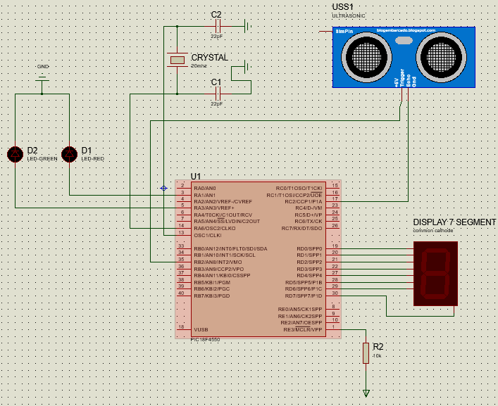 [/URL] [/URL]
Now the explanations:
--------------------
- Components used:
PIC18F4550
HC-SR04 Ultrasonic Sensor
Crystal: 20MHz
Display 7 segment common cathode
Green and Red LED
(Edit: I recommend to put a 1k resistor with the leds to don't burn it. I'm sorry but I forget to put them in Proteus)
--------------------
How it works:
If distance meassured is between 10cm and 4m, then GREEN LED HIGH and RED LED LOW. Also display 3 in the 7 segment display
else GREEN LED LOW and RED LED HIGH. Also display 4 in the 7 segment display.
After the meassure and the results, display 5 only to check that the code arrives to the end (i used for debugging, to see if the code goes to the end of the while. You can avoid it if you want).
If someone has some dudes write here and I will try to answer correctly. And if this post was useful for you, please comment it here. With your comment people could see that this project is working good!
Thanks to this forum and the people here, who really help to this community. |
|
|
doguhanpala
Joined: 05 Oct 2016
Posts: 120
|
|
| Posted: Wed Jul 10, 2019 5:05 am |
|
|
Hello,
I have tried the code with a few changes but i could not make it work.
I am using usb communication instead of rs232.
I use my ccp1 pin on something else so i want to use the ccp2(RB3) pin. there is also RC2 pin on CCP2 but i dont want to use it.
I have changed the CCP1s to CCP2. I have tried the code and i get stuck at
| Code: | | while (!interrupt_active(INT_CCP2) && !interrupt_active(INT_TIMER1)); |
I see the float value on putty but there is no t. I am assuming there is something wrong on my pin definitions. how should i make the pic know that i want to use RB3 instead of RC2.
Note: I am sure that sensor works, i have checked with scope and saw the signal on echo pin after sending pulse to trigger pin.
This is my code
| Code: | #if !defined(__PCH__)
#error USB CDC Library requires PIC18
#endif
#include <18F4550.h>
#DEVICE ADC=10
#fuses HSPLL,NOWDT,MCLR,PROTECT,NOLVP,NODEBUG,NOBROWNOUT,USBDIV,PLL5,CPUDIV1,VREGEN
#use delay(clock=48000000)
//#include <usb_bootloader.h>
#include "usb_cdc.h"
#define rp_getc usb_cdc_getc
#define rp_putc usb_cdc_putc
#define BLUE_LED PIN_D5 //Blue LED
#define RED_LED PIN_D6 //Red LED
#define TRIGGER PIN_B2 //any suitable pin
#define ECHO PIN_B3 //CCP2 input
float distance=0;
int value;
float my_value = 3.8;
void main()
{
usb_cdc_init();
usb_init();
output_low(TRIGGER);
setup_ccp1(CCP_OFF);
setup_ccp2(CCP_CAPTURE_FE);
setup_comparator(NC_NC_NC_NC);
set_timer1(0); //clear timer
CCP_2=0; //clear CCP;
clear_interrupt(INT_CCP2);
clear_interrupt(INT_TIMER1); setup_timer_1(T1_INTERNAL | T1_DIV_BY_8); //calc above
output_high(RED_LED);
while (true)
{
delay_ms(500);
output_low(RED_LED);
usb_task();
value = rp_getc();
delay_ms(20);
if(value == 'a')
{
printf(rp_putc, "%f",my_value);
output_high(BLUE_LED);
output_high(TRIGGER);
delay_us(20);
output_low(TRIGGER);
delay_us(5);
while (!interrupt_active(INT_CCP2) && !interrupt_active(INT_TIMER1));
if (interrupt_active(INT_CCP2))
{
printf(rp_putc,"t"); //Here an edge was seen
distance=(int32)CCP_2*4/55; //this gives integer distance in mm - 4m=55555 counts
distance=distance/10; //conversion distance from mm to cm
if (distance>10 && distance<400)
{
output_low(BLUE_LED);
output_high(RED_LED);
}
else
{
output_low(RED_LED);
output_high(BLUE_LED);
}
// delay_ms(100); //pause before next reading
printf(rp_putc, "%ld\n\r",distance);
}
}
}
} |
thank you so much! |
|
|
gaugeguy
Joined: 05 Apr 2011
Posts: 288
|
|
| Posted: Wed Jul 10, 2019 5:55 am |
|
|
That is done with a fuse setting. Check the fuses in the pic header file.
CCP2B3 or CCP2C1 |
|
|
|
|
You cannot post new topics in this forum
You cannot reply to topics in this forum
You cannot edit your posts in this forum
You cannot delete your posts in this forum
You cannot vote in polls in this forum
|
Powered by phpBB © 2001, 2005 phpBB Group
|

