| View previous topic :: View next topic |
| Author |
Message |
Ttelmah
Joined: 11 Mar 2010
Posts: 19215


|
|
 Posted: Sat Jul 28, 2018 8:32 am Posted: Sat Jul 28, 2018 8:32 am |
 |
|
| The link he gives though does not show how the shield is connected. This is vital. If (for instance) he has the grounds connected through the shield, then this can result in current flowing in the shield, which then induces signals into the internal lines.... |
|
 |
ufkyldrm
Joined: 21 May 2018
Posts: 27
|
|
| Posted: Sun Jul 29, 2018 6:05 am |
|
|
| Mike Walne wrote: | Mr. T. and I suspect that you are not understand the nature of the problem you're facing.
I do not think you are being devious in any way.
You started by complaining of problems caused by a "big machine".
But you are not supplying the necessary detail of your system.
You've told us that your components are as below :-
| Code: |
5V ----WWWWWW---------- ---------------------------------- ------|
| One of twisted pair cores |
\ |
Reed Switch \ ---------------------------------- ------|
| Other twisted pair core |
| |
0V--------------------- ---------------------------------- ------|
Screen
Signal Source Screened Twisted Pair Cable PIC
|
However, you are not telling us HOW they are connected.
I've left blank spaces for you to fill in.
Mike |
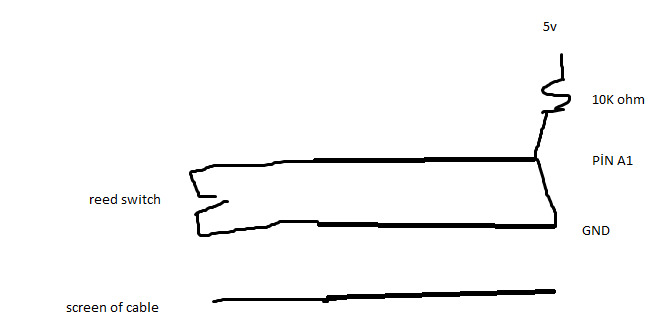
I guess ı m really noob.
I have no connection for screen. png is linked.
Tomorrow I will connect 5v and gnd with capacitor for filtering.
I ll chance resistor 10 K to 1 K ohm.
I ll connect screen to gnd. I dont know is it good idea?
What is shield?
Last edited by ufkyldrm on Sun Jul 29, 2018 6:10 am; edited 1 time in total |
|
|
ufkyldrm
Joined: 21 May 2018
Posts: 27
|
|
| Posted: Sun Jul 29, 2018 6:05 am |
|
|
| Ttelmah wrote: | | The link he gives though does not show how the shield is connected. This is vital. If (for instance) he has the grounds connected through the shield, then this can result in current flowing in the shield, which then induces signals into the internal lines.... |
What is shield?
Is it screen of cable? |
|
|
ufkyldrm
Joined: 21 May 2018
Posts: 27
|
|
| Posted: Sun Jul 29, 2018 6:09 am |
|
|
| Ttelmah wrote: | | I'm particularly suspicious there may be connections at both end of the shield, which can then result in current flowing in the shield, which can make it worse than useless. Also that the actual drive may be something like 4K7 or 10KR, which means that the line when pulled (up?) by this, is quite high impedance. |
Hi my hero.
Shied and screen are same ı guess..
There is no connection for screen.
Should I connect just one side of the shied to GND_? |
|
|
Ttelmah
Joined: 11 Mar 2010
Posts: 19215
|
|
| Posted: Sun Jul 29, 2018 7:09 am |
|
|
The whole point of shielded cables is that the shield _must_ be connected to a really good ground at one end. Preferably the PIC end in this case. It then acts at least partially as a Faraday shield.
It picks up external EMI, and conducts it to ground. If it is not grounded, noise will couple into it, and it'll then be coupled into the internal lines. Not what is wanted.
Ground this, reduce your pull-up. and add perhaps a 0.1uF between the signal and ground at the PIC end. Honestly 10K, is much too large. Something like 1K or 1K2 is a better value. |
|
|
|


